INSTALLATION MANUAL English SYSTEM Inverter Air Conditioners Français MODELS Ceiling-mounted Duct type FXMQ07PVJU FXMQ09PVJU FXMQ12PVJU FXMQ18PVJU FXMQ24PVJU FXMQ30PVJU Español FXMQ36PVJU FXMQ48PVJU READ THESE INSTRUCTIONS CAREFULLY BEFORE INSTALLATION. KEEP THIS MANUAL IN A HANDY PLACE FOR FUTURE REFERENCE. LIRE SOIGNEUSEMENT CES INSTRUCTIONS AVANT L’INSTALLATION. CONSERVER CE MANUEL A PORTEE DE MAIN POUR REFERENCE ULTERIEURE. LEA CUIDADOSAMENTE ESTAS INSTRUCCIONES ANTES DE INSTALAR.
VRV SYSTEM Inverter Air Conditioners CONTENTS 1. 2. 3. 4. 5. 6. 7. 8. 9. 10. SAFETY CONSIDERATIONS.......................................... 1 BEFORE INSTALLATION ................................................ 3 SELECTING INSTALLATION SITE.................................. 4 PREPARATIONS BEFORE INSTALLATION .................... 5 INDOOR UNIT INSTALLATION ....................................... 6 REFRIGERANT PIPING WORK...................................... 7 DRAIN PIPING WORK ...........................
• Before touching electrical parts, turn off the unit. • Be sure to install a ground fault circuit interrupter if one is not already available. This helps prevent electrical shocks or fire. • Securely fasten the outside unit terminal cover (panel). If the terminal cover/panel is not installed properly, dust or water may enter the outside unit causing fire or electric shock.
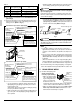
2. BEFORE INSTALLATION • When moving the unit while removing it from the carton box, be sure to lift it by holding on to the four lifting lugs without exerting any pressure on other parts, especially, the refrigerant piping, drain piping, flanges and other resin parts. • Be sure to check the type of R410A refrigerant to be used before installing the unit. (Using an incorrect refrigerant will prevent normal operation of the unit.
2-3 OPTIONAL ACCESSORIES b. Items to be checked at time of delivery • These is one type of remote controller: wired. Items to be checked NOTE Are you sure the control box lid, air filter, air inlet grille, and air outlet grille are mounted? • If you wish to use a remote controller that is different from the above, select a suitable remote controller after consulting catalogs and technical materials.
• Install the indoor and outdoor units, power supply wiring and connecting wires at least 3.3 ft away from televisions or radios in order to prevent image interference or noise. (Depending on the radio waves, a distance of 3.3 ft may not be sufficient enough to eliminate the noise.) • In the case of the installation of a wireless remote controller, the transmission distance of the wireless remote controller may be shortened if the room has a fluorescent light of electronic lighting type (i.e.
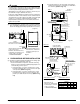
(2) Mount the canvas ducts to the air outlet and inlet so that the vibration of the air conditioner will not be transmitted to the duct or ceiling. Apply a sound-absorbing material (insulation material) to the inner wall of the duct and vibration insulation rubber to the hanging bolts (refer to 8. DUCT WORK). (3) Open installation holes (if the ceiling already exists). • Open the installation holes on the ceiling.
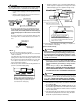
CAUTION • Use the level and check that the unit is installed horizontally. (4-directions) • In the case of using a vinyl tube in place of the level, put the both edges of the vinyl tube in close contact with the bottom of the product to make levelness adjustment. If the unit is installed at a slant with the drain pipe side set high, in particular, the float switch will not operate normally and water leakage may result. (1) Connect the piping. • The outdoor unit is filled with refrigerant.
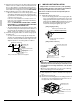
Table 2 Pipe size Further tightening angle Recommended arm length of tool φ 1/4 60 to 90 degrees Approx. 5-7/8 in. φ 3/8 60 to 90 degrees Approx. 7-7/8 in. φ 1/2 30 to 60 degrees Approx. 9-13/16 in. φ 5/8 30 to 60 degrees Approx. 11-13/16 in. (2) On completion of installation work, check that there is no gas leakage. (3) Refer to the illustration on the right-hand side and be sure to perform heat insulation work on the piping joints after gas leakage checks. (Refer to Fig.
• The drain piping will be clogged with water and water leakage may result if the water is accumulated in the drain piping. • Select the diameter of the concentrated drain piping to suit the capacity of equipment connecting to the concentrated drain piping (see the equipment design sheet). Ceiling slab 12 in. max. • Conduct drain-up piping work if the gradient is insufficient. • Attach a support bracket at 3.3 to 4.9 ft intervals for the prevention of piping deflection. 3.3 - 4.
The drainage can be checked with the water level change in the drain pan through the water inlet. CAUTION • Do not touch the drain pump. Otherwise, an electric shock may be received. • Do not impose external force on the float switch. Otherwise, a failure may result. 5. On completion of the drainage check, shut off the power supply and disconnect the power supply line. 6. Put the control box lid to the original position. [After electrical work] • After completion of 8.
9. 9-1 ELECTRIC WIRING WORK 9-3 GENERAL INSTRUCTIONS • All field supplied parts and materials and electric works must conform to local codes. • Use copper wire only. • For electric wiring work, refer to also “Wiring diagram” attached to the control box lid. • For remote controller wiring details, refer to the installation manual attached to the remote controller. • All wiring must be performed by an authorized electrician. • This system consists of multiple indoor units.
(2) Lay the wires in the control box through the wire inlet on the side of the control box. Conduit (Field supply) Lock nut (Field supply) (3) Follow the instructions below, and lay the wires in the control box. Fix the wires with clamp (8) to the wire fixing bracket provided to the control box. Transmission wiring (Low voltage) Remote controller wiring (Low voltage) Insert the cord into the wire clips provided with the control box.
(4) Put the control box lid, and wrap the wire sealing material (Small) (10) around the conduit so as to block the wire through holes. Wire through holes 10-2 WIRING EXAMPLE WARNING Install a ground fault circuit interrupter. The installation of a ground fault circuit interrupter is imperative for the prevention of electric shocks and fire accidents. No.
No. 3 system: When including BS unit Power supply single phase 60Hz 208/230V Outdoor unit BS unit (2) Set the main/sub switch on one of the remote controller PCBs to sub. (Keep the switch of the other remote controller PCB set to main.) L1 L2 IN/D OUT/D F1 F2 F1 F2 OUT/D IN/D F1 F2 F1 F2 (Factory setting) S M Remote controller PC board Only one remote controller needs to be changed if factory settings have remained untouched.
Make sure the control box lids are closed on the indoor and outdoor units. Field setting must be made from the remote controller in accordance with the installation condition. • Setting can be made by changing the “MODE NO.”, “FIRST CODE NO.”, and “SECOND CODE NO.”. • For setting and operation, refer to the “FIELD SETTING” in the installation manual of the remote controller. SECOND CODE NO. MODE NO. FIRST CODE NO. SETTING FIELD SET MODE • Set the remote controller to the “FIELD SET MODE”.
*1 The FXMQ18 · 24 · 30 · 36PVJU cannot be set to 0.12 inWG. *2 The FXMQ07 · 09 · 12PVJU cannot be set to 0.44-0.80 inWG. *3 The FXMQ48PVJU cannot be set to 0.12 inWG and 0.60-0.80 inWG. Table 4 External Static Pressure MODE NO. FIRST CODE NO. SECOND CODE NO. 0.12 inWG (*1)(*3) 01 0.20 inWG 02 0.24 inWG 03 0.28 inWG 04 0.32 inWG 05 0.36 inWG 06 0.40 inWG 07 0.44 inWG (*2) 13 (23) 06 12. TEST OPERATION Refer to the installation manual of the outdoor unit.
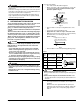
1645 Wallace Drive, Suite 110 Carrollton, TX 75006 info@daikinac.com www.daikinac.