00_CV_3P086156-8X.fm Page 1 Tuesday, April 7, 2009 4:45 PM INSTALLATION MANUAL English SYSTEM Inverter Air Conditioners Deutsch MODELS Ceiling-mounted cassette type (corner model) FXKQ25MVE FXKQ32MVE FXKQ40MVE FXKQ63MVE FXKQ25MAVE FXKQ32MAVE FXKQ40MAVE FXKQ63MAVE Français Español Italiano READ THESE INSTRUCTIONS CAREFULLY BEFORE INSTALLATION. KEEP THIS MANUAL IN A HANDY PLACE FOR FUTURE REFERENCE. LESEN SIE DIESE ANWEISUNGEN VOR DER INSTALLATION SORGFÄLTIG DURCH.
EN60335-2-40, FXZQ20MVE, FXZQ25MVE, FXZQ32MVE, FXZQ40MVE, FXZQ50MVE FXCQ20MVE, FXCQ25MVE, FXCQ32MVE, FXCQ40MVE, FXCQ50MVE, FXCQ63MVE, FXCQ80MVE, FXCQ125MVE FXMQ40MVE, FXMQ50MVE, FXMQ63MVE, FXMQ80MVE, FXMQ100MVE, FXMQ125MVE, FXMQ200MVE, FXMQ250MVE FXLQ20MVE, FXLQ25MVE, FXLQ32MVE, FXLQ40MVE, FXLQ50MVE, FXLQ63MVE FXNQ20MVE, FXNQ25MVE, FXNQ32MVE, FXNQ40MVE, FXNQ50MVE, FXNQ63MVE FXHQ32MVE, FXHQ63MVE, FXHQ100MVE FXSQ20MVE, FXSQ25MVE, FXSQ32MVE, FXSQ40MVE, FXSQ50MVE, FXSQ63MVE, FXSQ80MVE, FXSQ100MVE, FXSQ125MVE
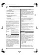
01_EN_3P086156-8X.fm Page 1 Wednesday, April 8, 2009 3:56 PM VRV SYSTEM Inverter Air Conditioners CONTENTS 1. 2. 3. 4. 5. 6. 7. 8. 9. SAFETY PRECAUTIONS................................................ 1 BEFORE INSTALLATION ................................................ 2 SELECTING INSTALLATION SITE ................................. 3 PREPARATIONS BEFORE INSTALLATION.................... 3 INDOOR UNIT INSTALLATION ....................................... 4 REFRIGERANT PIPING WORK .........................
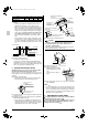
01_EN_3P086156-8X.fm Page 2 Wednesday, April 8, 2009 3:56 PM 4. Where flammable gas may leak, where there is carbon fibre or ignitable dust suspensions in the air, or where volatile flammables such as paint thinner or gasoline are handled. Operating the unit in such conditions may result in fire. • The air conditioner is not intended for use in a potentially explosive atmosphere. 2. Name Insulation for fitting Sealing pad Insulation for hanger bracket Quantity 1 each. 1 each. 4 pcs.
01_EN_3P086156-8X.fm Page 3 Wednesday, April 8, 2009 3:56 PM FOR THE FOLLOWING ITEMS, TAKE SPECIAL CARE DURING CONSTRUCTION AND CHECK AFTER INSTALLATION IS FINISHED. • Where sufficient clearance for installation and maintenance can be ensured. • Where there is no risk of flammable gas leakage. • Where piping between indoor and outdoor units is possible within the allowable limit. (Refer to the installation manual for the outdoor unit.) a.
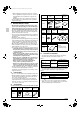
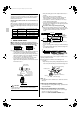
01_EN_3P086156-8X.fm Page 4 Wednesday, April 8, 2009 3:56 PM Model A B C D FXKQ25 · 32 · 40M(A)VE 1110 1150 1200 1240 FXKQ63M(A)VE 1310 1350 1400 1440 (2) Open a hole in the ceiling for installation. (Case of existing ceiling) • Use the paper pattern for installation which has been adjusted to the dimensions of the ceiling opening.
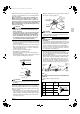
01_EN_3P086156-8X.fm Page 5 Wednesday, April 8, 2009 3:56 PM (When using a heat pump, the temperature of the gas piping can reach up to approximately 120°C, so use insulation which is sufficiently resistant.) 〈Also, in cases where the temperature and humidity of the refrigerant piping sections might exceed 30°C or RH80 %, reinforce the refrigerant insulation. (20 mm or thicker) Condensation may form on the surface of the insulating material.〉 〈Before ringging tubes, check which type of refrigerant is used.
01_EN_3P086156-8X.fm Page 6 Wednesday, April 8, 2009 3:56 PM Not recommendable but in case of emergency You must use a torque wrench but if you are obliged to install the unit without a torque wrench, you may follow the installation method mentioned below. After the work is finished, make sure to check that there is no gas leak. When you keep on tightening the flare nut with a spanner, there is a point where the tightening torque suddenly increases.
01_EN_3P086156-8X.fm Page 7 Wednesday, April 8, 2009 3:56 PM Be sure attach the electric parts box lid before turning on the powe. Next, press the inspection/test operation button “ TEST ” on the remote controller. The unit will engage the test operation mode. Press the operation mode selector button “ ” until selecting FAN OPERATION “ ”. Then, press the ON/OFF button “ ”. The indoor unit fan and drain pump will start up. Check that the water has drained from the unit.
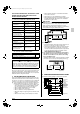
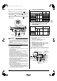
01_EN_3P086156-8X.fm Page 8 Wednesday, April 8, 2009 3:56 PM [ PRECAUTIONS ] NOTE 1: Details of terminal block for power supply LN Electric parts box Power supply wiring and ground wiring (*) Plastic clamp (Field wiring) NOTE 2: Details of terminal block for unit transmission wirings Remote controller wiring (*) (Field wiring) 1. Use round crimp-style terminals for connecting wires to the power supply terminal board. If unavailable, observe the following points when wiring.
01_EN_3P086156-8X.fm Page 9 Wednesday, April 8, 2009 3:56 PM 9-2 HIGH CEILING INSTALLATION 9-3 (1) This unit can be installed in ceilings up to 3.8 meters high. If the ceiling height exceeds 2.7 meters, however, connect the connector on the terminal board (A2P) of indoor units as shown in the figure below. Terminal board (A2P) WIRING EXAMPLE • Fit the power supply wiring of each unit with a switch and fuse as shown in the drawing.
01_EN_3P086156-8X.fm Page 10 Wednesday, April 8, 2009 3:56 PM 3. When including BS unit Power supply 220-240V 50Hz or 220V Power supply 220-240V Outdoor unit Control box IN/D OUT/D F1 F2 F1 F2 L N No. 3 System Wiring Method (See “ELECTRIC WIRING WORK”) (3) Remove the electric parts box lid. (4) Add remote control 2 (slave) to the terminal block for remote controller (P1, P2) in the electric parts box. (There is no polarity.) (Refer to Fig. 1 and 8-3.
01_EN_3P086156-8X.fm Page 11 Wednesday, April 8, 2009 3:56 PM 10. DECORATION PANEL INSTALLATION 12. TEST OPERATION Refer to the installation manual of the panels. Refer to the installation manual of the outdoor unit. • The operation lamp of the remote controller will flash when an malfunction occurs. Check the malfunction code on the liquid crystal display to identify the point of trouble.
00_CV_3P086156-8X.