
Service manual
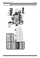
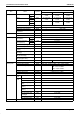
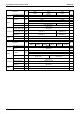
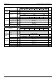

6L(1 :LULQJ'LDJUDPVIRU5HIHUHQFH
$SHQGL[
);$40009(0009(
3D034206A
PC
1.
: Terminal
: Field wiring
(Indoor unit)
Side
Front
Control box
: Connector
: Connector
NOTES
Power Supply
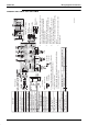
2. In case using central remote control, connect it to to the unit in
accordance with the attached installation manual.
3. Symbols show as follows.
(PNK:Pink WHT:White YLW:Yellow ORG:Orange Blu:Blue BLK: Black
RED:Red BRN:Brown GRY:Gray)
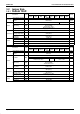
4. When connecting the input wires from outside, forced
off or on/off control operation can be selected by
remote control. In details, refer to the installation
manual attached the unit.
5. Remote control model varies according to the
combination system, confirm engineering data and
catalogs, etc. before connecting.
6. Confirm the method of setting the selector switch
(SS1, SS2) of wired remote control and infrared
remote control by installation manual and engineering
data, etc.
7. X24A is connected when the infrared remote control
kit is being used.
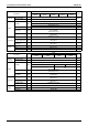
Wired remote
control
Note: 7
Note-7 Receiver/display unit
(Infrared remote control)
Note-4
Input from outside
Note-2
Transmission wiring
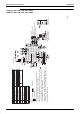
Indoor unit
A1P Printed circuit board
F1U Fuse ( B, 5A, 250V)
HAP Light emitting diode
(Service monitor-green)
M1S Motor (Swing flap)
M1F Motor (Indoor fan)
R1T Thermistor (Air)
R2T Thermistor (Coil-liquid pipe)
R3T Thermistor (Coil-gas pipe)
X1M Terminal block (Control)
X2M Terminal block (Power)
Y1E Electronic expansion valve
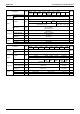
Power circuit
Receiver/Display unit (attached to
infrared remote control
A2P Printed circuit board
A3P Printed circuit board
BS1 Push button (On/Off)
H1P Light emitting diode (On-red)
H2P Light emitting diode
(Timer-green)
H3P Light emitting diode
(Filter sign-red)
H4P Light emitting diode
(Defrost-orange)
SS1 Selector switch (Main/Sub)
SS2 Selector switch
(Wireless address set)
Wired remote control
R1T Thermistor (Air)
SS1 Selector switch (Main/Sub)
Connector for optional switch
X15A Thermistor (Air)
X35A Connector (Group control adaptor)