
Service manual
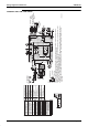
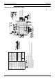

:LULQJ'LDJUDPVIRU5HIHUHQFH 6L(1
$SSHQGL[
);040000009(
3D039620
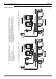
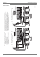
1.
2.
Terminal
Connector
Notes)
3. In case using central remote control, connect it to the unit
in accordance with the attached instruction manual.
4. When connecting the input wires from outside, forced off or on/off control operation can be selected
by remote control.
In details, refer to the installation manual attached the unit.
5. In case high E.S.P. operation change over the wiring connection from X2A as shown upper figure.
6. Symbols show as follows . (PNK:Pink WHT:White YLW:Yellow ORG:Orange BlU:Blue BLK: Black
RED:Red BRN:Brown GRY:Gray)
7. Use copper conductors only.
Field wiring
Power Supply
Input from outside
Note-4
Transmission wiring
central remote control
Note-3
Wired remote control
(optionel accessory)
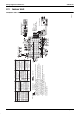
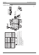
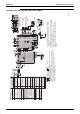
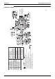
Electric parts box
Indoor unit
A1P Printed circuit board
A2P Terminal board
C1R Capacitor (M1F)
F1T Thermal Fuse
(153t) (M1F built-in
only 40-50 type)
F1U Fuse ( B, 5A, 250V)
40-50-63-80 type
F1U Fuse ( B, 5A, 250V)
100-125type
HAP Light emitting diode
(Service monitor-green)
K1R-K3R Magnetic relay (M1F)
KPR Magnetic relay (M1P)
M1F Motor (Indoor fan)
Q1M Thermo switch
(M1F Built-in
only 63-125 type)
R1T Thermistor (Air)
R2R-R3T Thermistor (Coil)
S1L Float switch
T1R Transformer (220-240V/22V)
X1M Terminal strip (Power)
X2M Terminal strip (Control)
Y1E Electronic
expansion valve
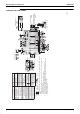
Optional parts
M1P Motor (Drain pump)
Wired remote control
SS1 Selector switch
(Main/Sub)
R1T Thermistor (Air)
Connector for optional parts
X18A Connector (Wiring adapter
for electrorical appendices)