
Service manual

:LULQJ'LDJUDPVIRU5HIHUHQFH 6L(1
$SSHQGL[
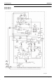
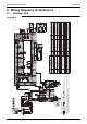
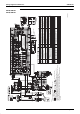
:LULQJ'LDJUDPVIRU5HIHUHQFH
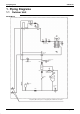
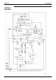
2XWGRRU8QLW
5;<40<%
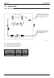
Detail of M1C
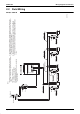
POWER SUPPLY
Cool/Heat Selector (Optional Accessory)
Indoor (F1) (F2)
Outdoor (F1) (F2)
(Back)
Switch box
Cool/Heat Selector
In-Out
Out-Out
Cool
Heat
Cool
Heat
Fan
L1-RED L2-WHT
N-BLKL3-BLU
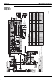
Notes:
Note:5
Note:4
(Front)
Note:4
A1P Printed Circuit Board (Main)
A2P Printed Circuit Board (Inv)
A3P Printed Circuit Board (Fan)
A4P Printed Circuit Board (Noise filter)
BS1 ~ 5 Push Button Switch (A1P)
(Mode, Set, Return, Test, Reset)
C1, 4 Capacitor (A2P)
DS1, 2 Dip Switch (A1P)
E1HC Crankcase Heater
F1U Fuse (500V, 6A) (A4P)
F1U, 2U Fuse (250V, 10A,
B
) (A1P)
H1P ~ 8P
Pilotlamp (Service monitor-orange) (A1P)
[H2P] Prepare, Test --- Flickering
Malfunction Detection light up
HAP
Pilotlamp (Service monitor-green) (A1P~3P)
K1M Magnetic contactor (M1C)
K1R Magnetic Relay (A2P)
K2R Magnetic Relay (K1M) (A2P)
K3R Magnetic Relay (Y1S) (A1P)
K6R Magnetic Relay (Y2S) (A1P)
K11R Magnetic Relay (Y3S) (A1P)
K13R Magnetic Relay (E1HC) (A1P)
K16R Magnetic Relay (Option Adaptor)
K1R Reactor
M1C Motor (Compressor)
M1F Motor (FAN)
PS Switching Power Supply (A2P)
Q1RP Phase Reversal Detect Circuit (A1P)
R1 Resistor (Current Limiting) (A2P)
R10 Resistor (Current Sensor) (A3P)
R133 Resistor (Current Sensor) (A2P)
R3, 4 Resistor (A2P)
R1T Thermistor (Fin) (A2P
R1T Thermistor (Air) (A1P)
R2T Thermistor (Suction)
R3T Thermistor (M1C Discharge)
R4T Thermistor (Heat exc. Deicer)
R5T Thermistor (Heat exc. Outlet)
R6T Thermistor (Liq. Pipe Receiver)
R7T Thermistor (Oil Pipe)
S1NPH Pressure Sensor (High)
S1NPL Pressure Sensor (Low)
S1PH Pressure Switch (High)
T1R Transformer (220-240V/20V)
V1CP Safety Devices Input (A1P)
V1R Diode Bridge (A2P)
V2R IGBT Power Module (A2P, A3P)
X1M Therminal Strip (Power Supply)
X1M Therminal Strip (Control) (A1P)
Y1E Electronic Expansion Valve
Y1S Solenoid Valve (Hot Gas)
Y2S Solenoid Valve (Receiver Gas Purge)
Y3S Solenoid Valve (4 Way Valve)
Z1C~3C Noise Filter (Ferrite Core)
Z1F Noise Filter (With Surge Absorber)
Cool/Heat Selector (KRC19-26A)
S1S Selector Switch (Fan/Cool • Heat)
S2S Selector Switch (Cool/Heat)
3D038590
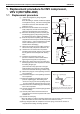
1. This wiring diagram is applied only to the outdoor unit.
2. :Field wiring.
3. : Terminal Strip : Connector : Terminal : Protective Earth (Screw)
4. When using the option adaptor, refer to the installation manual.
5. Refer to the installation manual, for connection wiring to indoor outdoor Transmission F1 • F2 Outdoor-Outdoor
Transmission F1 • F2
6. Refer to "Operation Caution Label" (On Switch box Cover), How to use BS1 ~ BS5 and DS1 • 2 Switch.
7. When operating, don't short circuit for protection device. (S1PH)
8. Colors BLK:Black RED:Red BLU:Blue WHT:White PNK:Pink YLW:Yellow BRN:Brown GRY:Gray GRN:Green ORG:Orange