
Service manual

7URXEOHVKRRWLQJE\,QGLFDWLRQRQWKH5HPRWH&RQWURO 6L(1
7URXEOHVKRRWLQJ
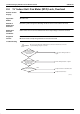
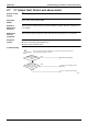
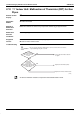
³C5´,QGRRU8QLW0DOIXQFWLRQRI7KHUPLVWRU57IRU*DV
3LSHV
5HPRWH&RQWURO
'LVSOD\
C5
$SSOLFDEOH
0RGHOV
$OOLQGRRUXQLWPRGHOV
0HWKRGRI
0DOIXQFWLRQ
'HWHFWLRQ
0DOIXQFWLRQGHWHFWLRQLVFDUULHGRXWE\WHPSHUDWXUHGHWHFWHGE\JDVSLSHWKHUPLVWRU
0DOIXQFWLRQ
'HFLVLRQ
&RQGLWLRQV
:KHQWKHJDVSLSHWKHUPLVWRUEHFRPHVGLVFRQQHFWHGRUVKRUWHGZKLOHWKHXQLWLVUXQQLQJ
6XSSRVHG
&DXVHV
'HIHFWRILQGRRUXQLWWKHUPLVWRU57IRUJDVSLSH
'HIHFWRILQGRRUXQLW3&ERDUG
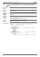
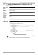
7URXEOHVKRRWLQJ
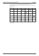
*5HIHUWRWKHUPLVWRUUHVLVWDQFHWHPSHUDWXUHFKDUDFWHULVWLFVWDEOHRQ3
(V2785)
Be sure to turn off power switch before connect or disconnect connector,
or parts damage may be occurred.
Caution
Replace the indoor unit PC board.
Connect the thermistor and turn
on again.
Replace the thermistor (R3T).
Connector is
connected to X11A
of the indoor unit PC
board.
Resistance is
normal when
measured after
disconnecting the thermistor (R3T)
from the indoor unit PC board.
(0.6kΩ~360kΩ)
NO
NO
YES
YES