EDUS 39 - 600 - F5 FXHQ-M Ceiling Suspended Type AMERICAS
EDUS39-600-F5 FXHQ-M Ceiling Suspended Type 1. 2. 3. 4. 5. 6. 7. Features ......................................................................................................2 Specifications ..............................................................................................3 Dimensions .................................................................................................4 Piping Diagrams..........................................................................................
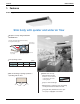
Features EDUS39-600-F5 1. Features External Appearance Slim body with quieter and wider air flow Adoption of newly designed QUIET STREAM FAN Uses the new quiet stream fan and many more quiet technologies.
EDUS39-600-F5 Specifications 2. Specifications Ceiling Suspended Type FXHQ12MVJU FXHQ24MVJU FXHQ36MVJU Cooling Capacity1 Model Btu/h 12,000 24,000 36,000 Heating Capacity2 Btu/h 13,500 27,000 40,000 White (10Y9/0.5) White (10Y9/0.5) White (10Y9/0.5) in (mm) 7-11/16×37-13/16×26-3/4” (177.8 x 954.9 x 679.5 mm) 7-11/16×55-1/8×26-3/4” (177.8 x 1400.2 x 679.5 mm) 7-11/16×62-5/8×26-3/4” (177.8 x 1590.7 x 679.5 mm) 2×12×15 3×12×15 2×12×15+2×10×15 ft² (m²) 1.96’ (0.60 m) 3.15’ (0.
Dimensions EDUS39-600-F5 3.
EDUS39-600-F5 Dimensions 3D049331 FXHQ24MVJU FXHQ-M 5
Dimensions EDUS39-600-F5 3D049332 FXHQ36MVJU 6 FXHQ-M
EDUS39-600-F5 Piping Diagrams 4.
Wiring Diagrams EDUS39-600-F5 5.
EDUS39-600-F5 Electric Characteristics 6.
Capacity Tables EDUS39-600-F5 7. Capacity Tables 7.1 Cooling Capacity FXHQ-M Cooling capacity Indoor Air Temp. °FWB Unit size Outdoor air temp. °FDB 12 24 36 75 79 83 87 91 95 99 103 75 79 83 87 91 95 99 103 75 79 83 87 91 95 99 103 61 64 67 70 72 75 TC SHC TC SHC TC SHC TC SHC TC SHC TC SHC MBh MBh MBh MBh MBh MBh MBh MBh MBh MBh MBh MBh 9.5 9.5 9.5 9.5 9.5 9.5 9.5 9.5 18.9 18.9 18.9 18.9 18.9 18.9 18.9 18.9 28.4 28.4 28.4 28.4 28.4 28.4 28.4 28.4 8.5 8.5 8.5 8.5 8.
EDUS39-600-F5 7.2 Capacity Tables Heating Capacity FXHQ-M Heating Capacity Indoor Air Temp. °FDB Indoor unit Outdoor Air Temp. °FDB 12 24 36 22.0 26.0 30.0 35.0 39.0 44.0 47.0 51.0 54.0 57.0 60.0 22.0 26.0 30.0 35.0 39.0 44.0 47.0 51.0 54.0 57.0 60.0 22.0 26.0 30.0 35.0 39.0 44.0 47.0 51.0 54.0 57.0 60.0 °FWB 20.0 24.0 28.0 32.0 36.0 40.0 43.0 47.0 50.0 53.0 56.0 20.0 24.0 28.0 32.0 36.0 40.0 43.0 47.0 50.0 53.0 56.0 20.0 24.0 28.0 32.0 36.0 40.0 43.0 47.0 50.0 53.0 56.
Air Velocity and Temperature Distributions EDUS39-600-F5 8.
EDUS39-600-F5 Air Velocity and Temperature Distributions FXHQ24M AIRFLOW DISTRIBUTIONS TEMPERATURE DISTRIBUTIONS FXHQ24M AIRFLOW DISTRIBUTIONS TEMPERATURE DISTRIBUTIONS 3D052939 FXHQ-M 13
Air Velocity and Temperature Distributions EDUS39-600-F5 FXHQ36M AIRFLOW DISTRIBUTIONS TEMPERATURE DISTRIBUTIONS FXHQ36M AIRFLOW DISTRIBUTIONS TEMPERATURE DISTRIBUTIONS 3D052940 14 FXHQ-M
EDUS39-600-F5 Sound Levels 9. Sound Levels Overall Ceiling Suspended Type Notes: Operation noise differs with operation and ambient conditions.
Installation EDUS39-600-F5 10. Installation Installation Example Air flow flap (at air outlet) Air outlet Discharge air Drain pipe Refrigerant pipe Inlet air Connection electric wire Suction grille Air filter (inside suction grille) Remote controller Grounding wire Wire from the unit into the ground to prevent electric shock. 1. SAFETY CONSIDERATIONS Read these SAFETY CONSIDERATIONS carefully before installing air conditioning equipment, and be sure to install it correctly.
EDUS39-600-F5 • Do not ground units to water pipes, telephone wires, or lightning rods because incomplete grounding can cause a severe shock hazard resulting in severe injury or death. Do not ground units to gas pipes because a gas leak can result in an explosion which could lead to severe injury or death. • Children playing with plastic bags face the danger of death by suffocation. Tear apart and throw away plastic packaging bags so that children cannot play with them. .
Installation Install the indoor unit as far away from fluorescent lamps as possible. • Arrange the drain hose to ensure smooth drainage. Incomplete drainage may cause leaks in the building and on furniture. • Radio interference may result if installed too close to other electrical devices. • Dismantling of the unit, and treatment of the refrigerant, oil, and other parts, should be done in accordance with the relevant local and national regulations. EDUS39-600-F5 2.
EDUS39-600-F5 Installation 2-1 ACCESSORIES Check that the following accessories are included with your unit. Name (1) Drain pipe Quantity 1 pc. (2) Metal clamp (3) Washer for hanger bracket (4) Clamp 8 pcs. 9 pcs. 1 pc. Does the power supply voltThe unit may malfunction or age correspond to that the components burn out. shown on the name plate? Are wiring and piping correct? The unit may malfunction or the components burn out. Is the unit safely grounded? Electric shock.
Installation EDUS39-600-F5 ∗ 1 3/16 or more ∗ 1 3/16 or more 4. PREPARATIONS BEFORE INSTALLATION (1) Relative position of holes for indoor unit, suspension bolt position, piping, and wiringg. Wiring hole Rear side pipe hole Air inlet Obstruction Floor 6 5 5/8 F G H A (Indoor unit) B (Suspension bolt pitch) C D (Length : in.) units is within the allowable limit. Refer to the installation manual for the outdoor unit.
EDUS39-600-F5 Installation (3-2) Remove the decoration panels (left and right) and the protection net. • After removing the securing screws for the decoration panels (one each), pull them forward in the direction of the arrowand remove them. (Refer to Fig. 3) • Remove the securing screws for the protection net. (Refer to Fig.
Installation 5. EDUS39-600-F5 INDOOR UNIT INSTALLATION It may be easier to attach accessory parts before installing the indoor unit. Therefore, please also read the instruction manuals provided with the accessory parts. As for the parts to be used for installation work, be sure to use the provided accessories and specified parts designated by Daikin AC. (1) Secure the hanger brackets to the suspension bolts. (Refer to Fig. 10) Refer to Figure 10.
EDUS39-600-F5 Installation 6-1 GENERAL INSTRUCTIONS Table 2 6-2 CONNECTING THE REFRIGERANT PIPE • Ensure outdoor unit is charged with refrigerant. • Use copper alloy seamless pipes. • Be sure to use both a spanner and torque wrench together, as shown in the drawing, when connecting or disconnecting pipes to/from the unit. (Refer to Fig. 13) • Refer to Table 2 to determine the proper tightening torque. • Refer to Table 2 for the dimensions of flare shape.
Installation EDUS39-600-F5 DANGER • Use of oxygen may cause an explosion resulting in serious injury or death. Only use nitrogen gas. (3) For piping facing right. • Cut out a slit hole on the decoration panel (right) and set the pipe. (Refer to Fig. 17) CAUTION • Be sure to insulate any field piping all the way to the piping connection inside the unit. Any exposed piping may cause condensate or a burn if touched.
EDUS39-600-F5 Installation • When doing this, block any gaps between the pipe penetration lid and the pipes by using putty to prevent dust from entering the indoor unit. NOTE DRAIN PIPING WORK (1) Carry out the drain piping. • Make sure piping provides proper drainage. • You can select whether to bring the drain piping out from the rear right or right. For rear right-facing and right-facing situations, refer to Section6. REFRIGERANT PIPING WORK on Page 188.
Installation EDUS39-600-F5 (2) Check to make sure the water flows smoothly after piping is complete. • Slowly pour 600ml of drain-checking water into the drain pan through the air outlet. Plastic container for pouring Air outlet 8-2 ELECTRICAL CHARACTERISTICS Units Model Power supply Hz Volts Voltage range 60 208230V Max. 253V Min. 187V FXHQ12MVJU FXHQ24MVJU FXHQ36MVJU MCA MFA Fan motor W FLA 0.8 15 62 0.6 1.0 15 130 0.8 1.4 15 130 1.1 MCA: Min. Circuit Amps (A);MFA: Max.
EDUS39-600-F5 Installation • Attach the plastic bushing (10) for remote controller wiring. • Insert the conduit for power supply wire in the conduit hole, and fix it with the lock nut. wire together with the transmission wire to the anchor. (Refer to Fig. 27, 28, 29) Refer to Fig.
Installation EDUS39-600-F5 COMPLETE SYSTEM EXAMPLE (3 systems) CAUTION • To avoid a short circuit in the electric parts box, be sure to apply sealing material or putty (not included) to the wiring hole to prevent the infiltration of water, insects, or other small creatures. Power supply Power supply wire Transmission wire Switch Main switch Fuse NOTE BS unit (Only for Heat recovery system) 1. Use round crimp-style terminals for connecting wires to the power-supply terminal block.
EDUS39-600-F5 Installation 3. When including BS unit Power supply 208-230V 60Hz Control box IN/D OUT/D F1 F2 F1 F2 L1 L2 Decoration panel Power supply 208-230V Outdoor unit BS unit L1 L2 60Hz BS unit Control box Control box OUT/D IN/D F1 F2 F1 F2 OUT/D IN/D F1 F2 F1 F2 (ii) Protection net Hook (i) Indoor unit A L1 L2 P 1 P 2 F 1 F2 T 1 T 2 L1 L2 P1 P2 P 1 P 2 F 1 F2 T 1 T 2 (ii) Most downstream indoor unit P1 P2 Hook Remote controller (ii) Fig. 33 (i) NOTE 1.
Installation EDUS39-600-F5 lation manual attached to the wireless remote controller for setting instructions. • Connect the input from outside to terminals T1 and T2 of the terminal block for remote controller.. 11-2 CONTROLLING 1 INDOOR UNIT BY 2 REMOTE CONTROLLERS F2 • When using 2 remote controllers, one must be set to MAIN and the other to SUB.
EDUS39-600-F5 Installation 12. TEST OPERATION 11-4 CENTRALIZED CONTROL • For centralized control, it is necessary to designate the Group Number. For details, refer to the manual of each optional controllers for centralized control. SECOND CORD NO. Mode No. FIRST CORD NO. SETTING FIELD SET MODE • Set the remote controller to the FIELD SET MODE. For details, refer to HOW TO SET IN THE FIELD in the remote controller manual. • When in the FIELD SET MODE, select mode No. 12, then set the FIRST CODE NO.
Installation Diagnose with the display on the liquid crystal display remote controller. 1. With the wired remote controller:. When the operation stops due to trouble, the operation lamp flashes and and the malfunction code is indicated in the liquid crystal display. In such a case, diagnose by referring to the table on the malfunction code list. In case of group control, the unit No. is displayed so that the indoor unit No. with the trouble can be recognized. 2.
EDUS39-600-F5 Installation Instantaneous overcurrent (outdoor) L5 L8 L9 Compressor motor grounded or short circuit; inverter PCB error Compressor overcurrent or compressor motor wire cut Compressor possibly locked LC Communication error between inverter and outdoor control unit P1 Open-phase (outdoor) P3 PC board temperature sensor malfunction (outdoor) P4 Radiation fin temperature sensor error PJ Capacity setting error (outdoor) or nothing programmed in the data hold IC.
Accessories EDUS39-600-F5 11. Accessories Standard Accessories Check that the following accessories are included with your unit. Name (1) Drain pipe (2) Metal clamp (3) Washer for hanger bracket (4) Clamp Quantity 1 pc. 1 pc. 8 pcs. 9 pcs. Shape Name (5) Paper pattern for installation Insulation pipe cover Sealing pad Quantity 1 pc. 1 each 1 each (6) For gas pipe (8) Large (7) For liquid pipe (9) Small Shape Name (10) Resin bush (11) Insulating tube Quantity 1 pc. 3 pcs.
EDUS 39 - 600 - F2 FXDQ-M Slim Ceiling Mounted Duct Type AMERICAS 1645 Wallace Drive, Suite 110 Carrollton, TX75006 info@daikinac.com www.daikinac.com May 2007 EDUS39-600-F5 Printed in U.S.A.