
Specifications

Installation EDUS39-900A-F4
36 FXMQ-P
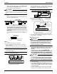
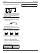
(2) Set the main/sub switch on one of the remote controller
PCBs to sub. (Keep the switch of the other remote control-
ler PCB set to main.)
9-4 COMPUTERISED CONTROL (FORCED OFF
AND ON/OFF OPERATION)
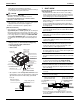
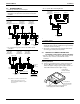
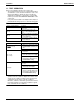
(1) Wire specifications and how to perform wiring
• Connect the input from outside to terminals T1 and T2
of the terminal block for remote controller.
(2) Actuation
• The following table explains FORCED OFF and ON/
OFF OPERATIONS in response to Input A.
(3) How to select FORCED OFF and ON/OFF OPERATION
• Turn the power on and then use the remote controller to
select operation.
9-5 CENTRALIZED CONTROL
• For centralized control, it is necessary to designate the
group No. For details, refer to the manual of each optional
controllers for centralized control.
10. FIELD SETTING
• Before the test operation of the outdoor unit as explained in
12. TEST OPERATION, be sure to make the following field
settings as explained in 11. FIELD SETTING.
Make sure the control box lids are closed on the indoor
and outdoor units.
Field setting must be made from the remote controller in
accordance with the installation condition.
• Setting can be made by changing the “MODE NO.”, “FIRST
CODE NO.”, and “SECOND CODE NO.”.
• For setting and operation, refer to the “FIELD SETTING” in
the installation manual of the remote controller.
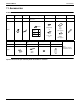
• Set the remote controller to the “FIELD SET MODE”.
For details, refer to the “HOW TO SET IN THE FIELD”,
in the remote controller manual.
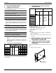
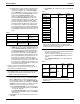
• When in the “FIELD SET MODE”, select “MODE NO.
12” , then set the “FIRST CODE NO.” to “1”. Then set
“SECOND CODE NO.” to “01” for FORCED OFF and
“02” for ON/OFF OPERATION. (FORCED OFF at fac-
tory set)
With Wireless Remote Controller Used
Set the wireless remote controller address before using the
wireless remote controller.
For the setting method of the address, refer to the operation
manual provided with the wireless remote controller.
• A “MODE NO.” is set on a group basis. To make a mode
setting on a room unit basis or check the setting made,
however, set the corresponding mode number in the
parentheses.
1. Settings for Optional Accessories
• In the case of connecting optional accessories, refer to
the operation manuals provided with the optional
accessories and make necessary settings.
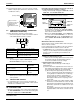
2. External Static Pressure Settings
Make settings in either method (a) or method (b) as
explained below.
(a) Use the airflow auto adjustment function to make set-
tings. Airflow auto adjustment: The volume of blow-off
air is automatically adjusted to the rated quantity.
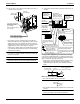
(1) Check that power supply wiring to the air condi-
tioner is completed along with duct installation. If a
closing damper is installed in the air-conditioning
system, make sure that the closing damper is
opened. Furthermore, check that the air filter as a
field supply is attached to the air passage on the
suction side.
(2) If there are a number of air outlets and inlets, adjust
the throttles so that the airflow rate of each air outlet
and inlet will coincide with the designed airflow rate.
At that time, operate the air conditioner in “fan oper-
ation mode”.
To change the airflow rate, press and set the airflow
adjustment button of the remote controller to HH, H,
or L.
Wire specification Sheathed vinyl cord or cable (2 wire)
Gauge AWG18-16
Length Max. 328 ft
External terminal
Contact that can ensure the minimum appli-
cable load of 15 V DC, 1 mA.
FORCED OFF
ON/OFF
OPERATION
Input “ON” stops operation (impossible by
remote controllers.)
Input OFF ON turns
ON unit.
Input OFF enables control by remote con-
troller.
Input ON OFF turns
OFF unit.
Only one remote
controller needs to be
changed if factory
settings have
remained untouched.
S
M
S
S
M
(Factory setting)
Remote controller
PC board
F2 T1 T2
FORCED
OFF
Input A
SETTING
MODE NO.
SECOND
CODE NO.
FIELD SET
MODE
FIRST
CODE NO.