
Specifications
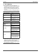

EDUS39-900A-F4 Installation
FXMQ-P 33
(2) Lay the wires in the control box through the wire inlet on
the side of the control box.
• Do not lay the remote controller wiring or transmission
wiring along with the power supply wiring or other electric
wiring in the same route. Separate the remote controller
wiring and transmission wiring at least 2 in. from the power
supply wiring or other electric wiring, or otherwise
malfunctions or failures may be caused by external electric
noise that may interfere with the remote controller wiring
and transmission wiring.
• For the installation and wiring of the remote controller, refer
to the remote controller installation manual provided with
the remote controller.
• For power supply wiring, refer to the wiring diagram as well.
• Be sure to connect the remote controller wiring and
transmission wiring correctly to the right terminal block.
(3) Follow the instructions below, and lay the wires in the con-
trol box.
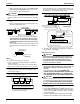
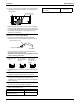
Routing power supply wiring and transmission wiring
Let the power supply wiring with a conduit pass through one
of the holes on the side cover, and let the transmission wiring
with a conduit pass through another hole.
• For protection from uninsulated live parts, thread the power
supply wiring or the transmission wiring through the
included insulation tube and secure it with the included
clamp.
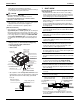
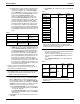
When use the insulation tube.
• Cut off the insulation tube as need length.
• Trim and lay the wiring neatly and attach the control box lid
securely.
• An electric shock or fire may result if the control box lid
catches any wiring or the wires push up the lid.
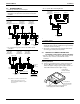
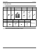
Low-voltage wiring inlet
Transmission wiring
(Low voltage)
Remote controller wiring
(Low voltage)
Lock nut
(Field supply)
Conduit
(Field supply)
High-voltage wiring inlet
Power supply wiring (High voltage)
Earth wiring (High voltage)
L1 L2
1P2P1F2F1T2T
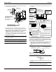
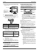
Fix the wires with
clamp (8) to the
wire fixing bracket
provided to the
control box.
Insert the cord into
the wire clips
provided with the
control box.
PROHIBITED
Never connect the power
supply wiring.
Connection method of remote
controller terminals (X2M)
• If stranded wires are used, do
not solder the front end of the
wires.
Twist and fix the upper part so
that the wires will not drop out.
Fix the cord with the
clamp (8) to the wire
fixing bracket provided
to the control box.
Remote controller
wiring (No polarity)
Power supply wiring
(High voltage)
Ground wiring
(High voltage)
Transmission wiring
(No polarity)
Transmission
wiring (Low voltage)
Remote controller
wiring (Low voltage)
Ground
Connection method of
power supply terminals
(X1M)
Insulation tube
(accessory (12))
Conduit
(field supply)
Insulation tube
(accessory (12))
Clamp
(accessory (8))
Power supply wiring
or
Transmission wiring
(3in.)
Cut off