
Specifications

EDUS39-900A-F4 Installation
FXMQ-P 31
pump will stop automatically in 10 minutes.)
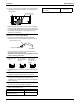
The drainage can be checked with the water level change
in the drain pan through the water inlet.
CAUTION
• Do not touch the drain pump.
Otherwise, an electric shock may be received.
• Do not impose external force on the float switch.
Otherwise, a failure may result.
5. On completion of the drainage check, shut off the power
supply and disconnect the power supply line.
6. Put the control box lid to the original position.
[After electrical work]
• After completion of 8. DUCT WORK provide
approximately 61 in
3
of water gradually into the drain pan
through the water inlet on the bottom of the drain socket,
and check that the water is drained while the air conditioner
is in cooling operation according to 11. FIELD SETTING
and 12. TEST OPERATION. Make sure that the water is
not spilled onto the electric parts of the drain pump and
others.
(3) Be sure to conduct heat insulation work on the fol-
lowing portions, or otherwise water leakage may
occur as a result of dew condensation.
• Drain piping indoors
• Drain socket
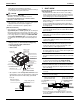
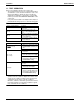
• On completion of the drainage check, refer to the follow-
ing illustration, and use the provided large sealing pad
(6) and heat insulate the metal clamp (1) and drain
hose (2).
7. DUCT WORK
Pay the utmost attention to the following items and con-
duct the ductwork.
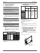
• Check that the duct will not be in excess of the setting
range of external static pressure for the unit. (Refer to the
technical datasheet for the setting range. Each model has
each setting range of external static pressure.)
• Attach a canvas duct each to the air outlet and air inlet so
that the vibration of the equipment will not be transmitted to
the duct or ceiling.
Use a sound-absorbing material (insulation material) for
the lining of the duct and apply vibration insulation rubber to
the hanging bolts.
• At the time of duct welding, perform the curing of the duct
so that the sputter will not come in contact with the drain
pan for the filter.
• If the metal duct pass through a metal lath, wire lath, or
metal plate of a wooden structure, separate the duct and
wall electrically.
• Be sure to heat insulate the duct for the prevention of dew
condensation. (Material: Glass wool or styrene foam;
Thickness: 31/32 in.)
• Be sure to attach the field supply air filter to the air inlet of
the unit or field supply inlet in the air passage on the air
suction side. (Be sure to select an air filter with a duct
collection efficiency of 50 weight percent.)
• Explain the operation and washing methods of the locally
procured components (i.e., the air filter, air inlet grille, and
air outlet grille) to the customer.
• Locate the air outlet grille on the indoor side for the
prevention of drafts in a position where indirect contact with
people.
• The air conditioner incorporates a function to adjust the fan
to rated speed automatically. (11. FIELD SETTING)
Therefore, do not use booster fans midway in the duct.
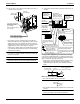
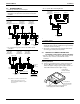
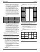
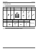
Connection method of ducts on air inlet and outlet sides.
• Connect the field supply duct in alignment with the inner
side of the flange.
• Connect the flange and unit with the flange connection
screw (3).
• Wrap aluminum tape around the flange and duct joint in
order to prevent air leakage.
• Connect the flange and unit with the flange connection
screw (3) regardless of whether the duct is connected to
the air inlet side.
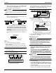
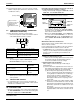
Water inlet
Drain socket
Drain pan
Control box lid
Terminal block for
power supply
Screw
Water inlet lid
Control box
Refrigerant piping
Air outlet
Socket for maintenance
(with rubber cap)
Drain pump position
Plastic water container
Make sure that the
seam faces upward.
Metal clamp (1)
(accessory)
Large sealing pad (6)
(accessory)
3/16 in. max.
Unit
Flange on air outlet side
(provided with the unit)
Insulation material
(field supply)
Canvas duct
(field supply)
Flange on air inlet side
(provided with the unit)
Insulation material
(field supply)
Air inlet
Air outlet
Screws for duct
flanges (3)
(accessory)
Screws
for duct
flanges (3)
(accessory)