
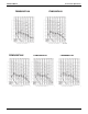
Specifications
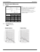
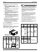
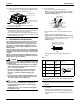

EDUS39-900A-F4 Installation
FXMQ-P 29
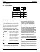
Ta bl e 2
(2) On completion of installation work, check that there is
no gas leakage.
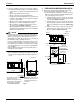
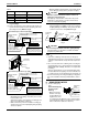
(3) Refer to the illustration on the right-hand side and be sure
to perform heat insulation work on the piping joints after
gas leakage checks. (Refer to Fig. 6)
• Use the insulation for fitting (4) and (5) provided to the
liquid piping and gas piping, respectively, and conduct
heat insulation work.
(Tighten both edges of the insulation for fitting (4) and
(5) for each joint with the clamp (8).)
• Make sure that the joint of the insulation for fitting (4)
and (5) for the joint on the liquid piping and gas piping
side faces upward.
• Wrap the middle sealing material (7) around the insula-
tion for fitting (4) and (5) for the joint (flare nut part).
CAUTION
• Be sure to perform the heat insulation of the local
piping up to the piping joint.
If the piping is exposed, dew condensation may result.
Furthermore, a burn may be caused if a human body
comes in contact with the piping.
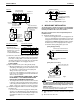
• Perform nitrogen substituent or apply nitrogen into the
refrigerant piping (see NOTE 1) in the case of refriger-
ant piping blazing (see NOTE 2). Then perform the flare
connection of the indoor unit. (Refer to Fig. 7)
CAUTION
•
Do not use any antioxidant at the time of piping blazing.
The piping may be clogged with a residual antioxidant
and parts may malfunction.
NOTE
1. At the time of blazing, set the pressure of nitrogen to
approximately 2.9 PSI (close to the pressure of a breeze
coming in contact with the cheek) with a decompression
valve.
2. Do not use flux at the time of blazing and connecting the
refrigerant piping. Use a copper phosphorus brazing alloy
(BCuP-2/BCu 93P-710/795), which does not require flux,
for blazing.
(Flux has a bad influence on the refrigerant piping. Chlo-
rine-based flux will cause piping corrosion. Furthermore, if
it contains fluorine, the flux will deteriorate refrigerant oil.)
• As for the branching of the refrigerant piping or refrigerant,
refer to the installation manual provided with the outdoor
unit.
6. DRAIN PIPING WORK
(1) Conduct drain piping
work.
Check that the piping
ensures proper
draining.
• Make sure that the
diameter of the pip-
ing excluding the ris-
ing part is the same
as or larger than the diameter of the connecting pipe
(vinyl chloride pipe with an outer diameter of 1-1/4 in.
and a nominal inner diameter of 31/32 in.).
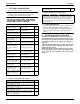
Pipe size Further tightening angle
Recommended arm length of
tool
1/4 60 to 90 degrees Approx. 5-7/8 in.
3/8 60 to 90 degrees Approx. 7-7/8 in.
1/2 30 to 60 degrees Approx. 9-13/16 in.
5/8 30 to 60 degrees Approx. 11-13/16 in.
Heat insulation procedure for gas piping
Insulation material
for piping
(on unit side)
Insulation material
for piping (field supply)
Make sure that
the seam faces
upward.
Clamp (8)
(accessory)
Gas pipe
Liquid pipe
Flare nut joint
Attached to
the surface.
Insulation for fitting (5) (accessory)
Middle sealing pad (7)
(accessory)
Wrap the insulation material
around the portion from the
surface of the main unit to the
upper part of the flare nut joint.
Insulation material
for piping (field supply)
Wrap the insulation material
around the portion from the
surface of the main unit to the
upper part of the flare nut joint.
Fig. 6
Heat insulation procedure for liquid piping
Insulation material
for piping
(on unit side)
Make sure that
the seam faces
upward.
Clamp (8)
(accessory)
Main unit
Flare nut joint
Attached to
the surface.
Insulation for fitting (4) (accessory)
Middle sealing pad (7)
(accessory)
Nitrogen
Refrigerant
piping
Part to be
brazed
Taping
Pressurereducing valve
hands
valve
Nitrogen
Fig. 7
Refrigerant
piping
Drain socket
Socket for
maintenance
(with rubber cap)