
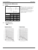
Specifications
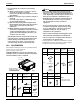

EDUS39-900A-F4 Installation
FXMQ-P 27
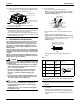
(2) Mount the canvas ducts to the air outlet and inlet so that
the vibration of the air conditioner will not be transmitted
to the duct or ceiling. Apply a sound-absorbing material
(insulation material) to the inner wall of the duct and vibra-
tion insulation rubber to the hanging bolts (refer to
8. DUCT WORK).
(3) Open installation holes (if the ceiling already exists).
• Open the installation holes on the ceiling. Lay the refrig-
erant piping, drain piping, power line, transmission wir-
ing, and remote controller wiring for the piping and
wiring connection port of the unit.
In the case of the installation of a wireless remote con-
troller, refer to the installation manual provided with the
wireless remote controller.
Refer to 6. REFRIGERANT PIPING WORK, 7. DRAIN
PIPING WORK, and 10. WIRING EXAMPLE AND
HOW TO SET THE REMOTE CONTROLLER.
• The ceiling framework may need reinforcement in order
to keep the ceiling horizontal and prevent the vibration
of the ceiling after the installation holes are opened. For
details, consult your construction or interior contractor.
(4) Install the hanging bolts. Make sure that the hanging bolts
are M10 in size.
• Use hole-in anchors if the hanging bolts already exist;
otherwise use embedded inserts and embedded foun-
dation bolts so that they will withstand the weight of the
unit. Adjust the distance to the ceiling surface in
advance.
4. INDOOR UNIT INSTALLATION
<It may be easier to install accessories (sold separately)
before installing the indoor unit. Refer to the installation
manuals provided to the accessories as well.>
Be sure to use the accessories and specified parts for
installation work.
(1) Temporally install the indoor unit.
• Connect the hanging brackets to the hanging bolts. Be
sure to use and tighten the nut and washer (11) for each
hanging bracket from both upper and lower sides of the
hanging bracket. (Refer to Fig. 3) At that time, the fall of
the washer (11) for the hanging bracket can be pre-
vented if the washing fixing plate (9) is used.
CAUTION
• During the installation work, perform the curing of the
air outlet and protect the resin drain pan of the indoor
unit from the intrusion of foreign substances, such as
welding spatters.
Otherwise, water leakage may occur as a result of damage,
such as hole damage, to the resin drain pan.
(2) Make adjustments so that the unit will be in the right posi-
tion.
(3) Check the level of the unit.
28 28
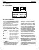
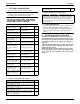
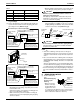
Inspection hatch
Inspection hatch 1
(17-3/4×17-3/4)
Inspection
hatch 2
Inspection hatch 3
(Same as the indoor
unit size +12 or more)
Control box
Control box
Control box
Inspection hatch
(Ceiling opening)
Ceiling
Axial direction view A-1 Axial direction view A-2
Min. D=B+12
Min. 8B
*H3=Min. 3/4
07 • 09 • 12 type 22
23-1/8
34
Model B C D
40
40-7/8
52
56
56-5/8
68
18 • 24 • 30 type
36 • 48 type
(length: in.)
A
Fig. 2-3
Case 2, 3
(Same as the
indoor unit
size or more)
• Determine the H3
dimension by maintaining a
downward slope of at least
1/100 as specified in
“7. DRAIN PIPING WORK”.
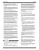
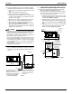
Note) All the above parts are field supplied.
Installation example
Ceiling slab
Anchor
Long nut or turn-buckle
Hanging bolt
Indoor unit
Washer (11) (accessory)
Part to be procured in the field
Washer fixing plate (9)
(accessory)
Insert
Tighten from above and below
(Double nut)
[Fixing hanging brackets]
[Fixing method of washers]
Fig. 3
Nut on the upper side