
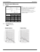
Specifications

Installation EDUS39-900A-F4
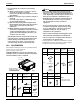
26 FXMQ-P
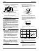
(1) Select an installation site where the following conditions
are fulfilled and that meets with your customer’s approval.
• A place where cool (warm) air is delivered to the entire
room.
• Where nothing blocks the air passage.
• Where condensate can be properly drained.
• If supporting structural members are not strong enough
to take the unit’s weight, the unit could fall out of place
and cause serious injury.
• Where the false ceiling is not noticeably on an incline.
• Where there is no risk of flammable gas leakage.
• Where sufficient clearance for maintenance and ser-
vice can be ensured. (Refer to Fig. 2-1)
• Where piping between indoor and outdoor units is pos-
sible within the allowable limit. (Refer to the installation
manual of the outdoor unit.)
CAUTION
• Install the indoor and outdoor units, power supply wiring
and connecting wires at least 3.3 ft away from televisions or
radios in order to prevent image interference or noise.
(Depending on the radio waves, a distance of 3.3 ft may not
be sufficient enough to eliminate the noise.)
• In the case of the installation of a wireless remote control-
ler, the transmission distance of the wireless remote con-
troller may be shortened if the room has a fluorescent light
of electronic lighting type (i.e., an inverter or rapid-start flu-
orescent light).
Keep the distance between the receiver and the fluores-
cent light as far as possible.
(2) Use hanging bolts to install the indoor unit. Check that the
place of installation withstands the weight of the indoor
unit. Secure the hanging bolts with proper beams if nec-
essary.
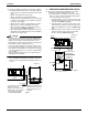
3. PREPARATIONS BEFORE INSTALLATION
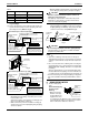
(1) Check the positional relationship between the ceiling
opening hole and the hanging bolt of the unit.
• For the maintenance, inspection, and other servicing
purposes of the control box and drain pump, prepare
one of the following service spaces.
1. Inspection hatch 1 (17-3/4 × 17-3/4) for the control
box and a minimum space of 12 in. for the lower part
of the product. (Refer to Fig. 2-2)
2. Inspection hatch 1 (17-3/4 × 17-3/4) for the control
box and inspection hatch 2 for the lower part of the
product (see axial direction view A-1). (Refer to Fig.
2-3)
3. Inspection hatch 3 for the lower part of the product
and the lower part of the control box (see axial
direction view A-2). (Refer to Fig. 2-3)
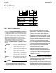
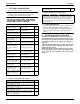
(length: in.)
Ceiling
Floor surface
The H1 dimension indicates the
height of the product.
Determine the H2 dimension by
maintaining a downward slope of
at least 1/100 as specified in
“7. DRAIN PIPING WORK”.
Min. 1Min. 12
Min. 18
Min. 99
Min. 28 (service space)
(If no ceiling board is provided.)
*H1=12
*H2=Min. 25
[Required installation place]
The dimensions indicate the
minimum required space of
installation.
Fig. 2-1
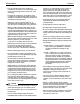
•
•
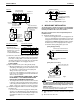
28
24-13/16
(Hanging bolt pitch)
Inspection hatch 1
(17-3/4×17-3/4)
Inspection hatch
Control box
Control box
Ceiling
B
C
(Hanging bolt pitch)
Bottom of unit
Air inlet
Air outlet
Hanging bolt (× 4)
*H3=Min. 12
Fig. 2-2
Case 1
(length: in.)