EDUS 39 - 900A - F4 FXMQ-P Ceiling Mounted Duct Type AMERICAS
EDUS39-900A-F4 FXMQ-P Ceiling Mounted Duct Type 1. 2. 3. 4. 5. 6. Specifications ..............................................................................................2 Dimensions .................................................................................................5 Piping Diagrams..........................................................................................9 Wiring Diagrams........................................................................................
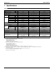
Specifications EDUS39-900A-F4 1. Specifications Ceiling Mounted Duct Type Model FXMQ07PVJU FXMQ09PVJU FXMQ12PVJU 1, 3 Cooling Capacity Btu/h 7,500 9,500 12,000 2, 3 Heating Capacity Btu/h 8,500 10,500 13,500 Galvanized Steel Plate Galvanized Steel Plate Galvanized Steel Plate 11-13/16 × 21-5/8 × 27-9/16 11-13/16 × 21-5/8 × 27-9/16 11-13/16 × 21-5/8 × 27-9/16 3×16×15 3×16×15 3×16×15 1.05 1.05 1.
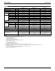
EDUS39-900A-F4 Specifications Ceiling Mounted Duct Type Model FXMQ18PVJU FXMQ24PVJU FXMQ30PVJU 1, 3 Cooling Capacity Btu/h 18,000 24,000 30,000 2, 3 Heating Capacity Btu/h 20,000 27,000 34,000 Galvanized Steel Plate Galvanized Steel Plate Galvanized Steel Plate 11-13/16 × 39-3/8 × 27-9/16 11-13/16 × 39-3/8 × 27-9/16 11-13/16 × 39-3/8 × 27-9/16 3×16×15 3×16×15 3×16×15 2.68 2.68 2.
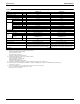
Specifications EDUS39-900A-F4 Ceiling Mounted Duct Type FXMQ36PVJU FXMQ48PVJU 1, 3 Cooling Capacity Model Btu/h 36,000 48,000 2, 3 Heating Capacity Btu/h 40,000 54,000 Galvanized Steel Plate Galvanized Steel Plate 11-13/16 × 55-1/8 × 27-9/16 11-13/16 × 55-1/8 × 27-9/16 3×16×15 3×16×15 4.12 4.
EDUS39-900A-F4 Dimensions 2.
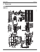
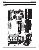
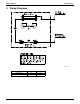
Dimensions EDUS39-900A-F4 6x5-7/8=35-1/4 3D065977 FXMQ18PVJU 6 FXMQ-P
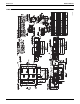
EDUS39-900A-F4 Dimensions 6x5-7/8=35-1/4 3D065978 FXMQ24PVJU FXMQ30PVJU FXMQ-P 7
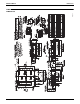
Dimensions EDUS39-900A-F4 8x5-7/8=47 FXMQ36PVJU FXMQ48PVJU or less 8 FXMQ-P
EDUS39-900A-F4 Piping Diagrams 3.
Wiring Diagrams EDUS39-900A-F4 4.
EDUS39-900A-F4 Electric Characteristics 5.
Capacity Tables EDUS39-900A-F4 6. Capacity Tables 6.1 Cooling Capacity FXMQ-P Outdoor Unit size air temp. 07 09 12 18 24 30 36 48 TC: SHC: 12 °FDB 75 79 83 87 91 95 99 103 75 79 83 87 91 95 99 103 75 79 83 87 91 95 99 103 75 79 83 87 91 95 99 103 75 79 83 87 91 95 99 103 75 79 83 87 91 95 99 103 75 79 83 87 91 95 99 103 75 79 83 87 91 95 99 103 [Cooling capacity] 61.0 °FWB TC SHC MBh MBh 5.9 5.7 5.9 5.7 5.9 5.7 5.9 5.7 5.9 5.7 5.9 5.7 5.9 5.7 5.9 5.7 7.5 6.9 7.5 6.9 7.5 6.9 7.5 6.9 7.5 6.
EDUS39-900A-F4 6.2 Capacity Tables Heating Capacity FXMQ-P Outdoor air temp. Unit size 07 09 12 18 24 30 36 [Heating capacity] °FDB 22.0 26.0 30.0 35.0 39.0 44.0 47.0 51.0 54.0 57.0 60.0 22.0 26.0 30.0 35.0 39.0 44.0 47.0 51.0 54.0 57.0 60.0 22.0 26.0 30.0 35.0 39.0 44.0 47.0 51.0 54.0 57.0 60.0 22.0 26.0 30.0 35.0 39.0 44.0 47.0 51.0 54.0 57.0 60.0 22.0 26.0 30.0 35.0 39.0 44.0 47.0 51.0 54.0 57.0 60.0 22.0 26.0 30.0 35.0 39.0 44.0 47.0 51.0 54.0 57.0 60.0 22.0 26.0 30.0 35.0 39.0 44.0 47.
Fan Performances EDUS39-900A-F4 7.
EDUS39-900A-F4 Fan Performances FXMQ18PVJU 3D066120B FXMQ24PVJU 3D066121B FXMQ-P 15
Fan Performances EDUS39-900A-F4 FXMQ30PVJU 3D066122B FXMQ36PVJU 3D066123B 16 FXMQ-P
EDUS39-900A-F4 Fan Performances FXMQ48PVJU 3D066449 FXMQ-P 17
Airflow Auto Adjustment Characteristics EDUS39-900A-F4 8. Airflow Auto Adjustment Characteristics FXMQ07PVJU / FXMQ09PVJU FXMQ12PVJU 3D066128A 3D066129B Notes: 1.To offset the reduction in airflow volume from the rated value, it is possible to adjust the airflow volume up to 10% using the Airflow Auto-Adjustment function during installation and commissioning 2. After completing the installation of the indoor unit ductwork, use the remote controller to set the airflow auto-adjustment. 3.
EDUS39-900A-F4 Airflow Auto Adjustment Characteristics FXMQ18PVJU FXMQ24PVJU 3D066130A FXMQ36PVJU FXMQ30PVJU 3D066131A 3D066132A FXMQ48PVJU 3D066133A 3D066450 Notes: 1. To offset the reduction in airflow volume from the rated value, it is possible to adjust the airflow volume up to 10% using the Airflow Auto-Adjustment function during installation and commissioning. 2. After completing the installation of the indoor unit ductwork, use the remote controller to set the airflow auto-adjustment. 3.
Sound Levels (Reference) EDUS39-900A-F4 9. Sound Levels (Reference) 9.1 Overall Location of microphone 3.3ft 6.6ft DUCT DUCT SUCTION 4.9ft DISCHARGE Notes: 1. The operating conditions are assumed to be standard (JIS conditions). Power source 208-230V, 60hz. 2. The operating values were obtained in an anechoic chamber (conversion values). 3.
EDUS39-900A-F4 Sound Levels (Reference) FXMQ018PVJU FXMQ24PVJU 4D068569 4D068568 FXMQ030PVJU FXMQ36PVJU 4D06857 FXMQ-P FXMQ48PVJU 4D068571 4D068572 21
Installation EDUS39-900A-F4 10. Installation 10.1 Center of Gravity 4D065975 10.2 Safety Considerations Read these SAFETY CONSIDERATIONS for Installation carefully before installing air conditioning equipment. After completing the installation, make sure that the unit operates properly during the startup operation. Instruct the customer on how to operate and maintain the unit. Inform customers that they should store this Installation Manual with the Operation Manual for future reference.
EDUS39-900A-F4 • Use only specified accessories and parts for installation work. Failure to use specified parts may result in water leakage, electric shocks, fire, or the unit falling. • Install the air conditioner on a foundation strong enough that it can withstand the weight of the unit. A foundation of insufficient strength may result in the unit falling and causing injuries. • Take into account strong winds, typhoons, or earthquakes when installing.
Installation EDUS39-900A-F4 • Do not install the air conditioner in the following locations: (a) Where a mineral oil mist or oil spray or vapor is produced, for example, in a kitchen. Plastic parts may deteriorate and fall off or result in water leakage. (b) Where corrosive gas, such as sulfurous acid gas, is produced. Corroding copper pipes or soldered parts may result in refrigerant leakage. (c) Near machinery emitting electromagnetic waves.
EDUS39-900A-F4 1. Installation OPTIONAL ACCESSORIES Did you deliver instruction manual, if any, for the field supplies to the customer? • These is one type of remote controller: wired. • If you wish to use a remote controller that is different from the above, select a suitable remote controller after consulting catalogs and technical materials. FOR THE FOLLOWING ITEMS, TAKE SPECIAL CARE DURING CONSTRUCTION AND CHECK AFTER INSTALLATION IS FINISHED. If not properly done, what is likely to occur.
Installation EDUS39-900A-F4 CAUTION 3. PREPARATIONS BEFORE INSTALLATION (1) Check the positional relationship between the ceiling opening hole and the hanging bolt of the unit. • For the maintenance, inspection, and other servicing purposes of the control box and drain pump, prepare one of the following service spaces. 1. Inspection hatch 1 (17-3/4 × 17-3/4) for the control box and a minimum space of 12 in. for the lower part of the product. (Refer to Fig. 2-2) 2.
EDUS39-900A-F4 Installation Installation example Case 2, 3 Control box Ceiling slab Anchor *H3=Min. 3/4 Inspection hatch (Ceiling opening) Long nut or turn-buckle Hanging bolt Indoor unit Inspection hatch A Inspection hatch 1 (17-3/4×17-3/4) Min. D=B+12 Min. 8 Inspection hatch 3 (Same as the indoor unit size +12 or more) Control box B Control box 28 Note) All the above parts are field supplied.
Installation EDUS39-900A-F4 (4) Remove the washer fixing plates for the falling prevention of the washers for the hanging brackets, tighten the nuts on the upper side, and securely fix the unit. Hanging bracket (1) Connect the piping. • The outdoor unit is filled with refrigerant. • When connecting or disconnecting piping to or from the unit, be sure to use two spanners and two torque wrenches. (Refer to Fig.
EDUS39-900A-F4 Installation Table 2 Pipe size Further tightening angle Recommended arm length of tool 1/4 60 to 90 degrees Approx. 5-7/8 in. 3/8 60 to 90 degrees Approx. 7-7/8 in. 1/2 30 to 60 degrees Approx. 9-13/16 in. 5/8 30 to 60 degrees Approx. 11-13/16 in. (2) On completion of installation work, check that there is no gas leakage. (3) Refer to the illustration on the right-hand side and be sure to perform heat insulation work on the piping joints after gas leakage checks.
Installation EDUS39-900A-F4 • Make sure that the piping is short enough with a downward slope of at least 1/100 and that there is no air bank formed. No drain trap is required. • Select the diameter of the concentrated drain piping to suit the capacity of equipment connecting to the concentrated drain piping (see the equipment design sheet). CAUTION Ceiling slab • Conduct drain-up piping work if the gradient is insufficient. • Attach a support bracket at 3.3 to 4.
EDUS39-900A-F4 Installation pump will stop automatically in 10 minutes.) The drainage can be checked with the water level change in the drain pan through the water inlet. CAUTION • Do not touch the drain pump. Otherwise, an electric shock may be received. • Do not impose external force on the float switch. Otherwise, a failure may result. 5. On completion of the drainage check, shut off the power supply and disconnect the power supply line. 6. Put the control box lid to the original position.
Installation 8. EDUS39-900A-F4 ELECTRIC WIRING WORK 8-1 8-3 SPECIFICATIONS FOR FIELD SUPPLIED FUSES AND WIRE GENERAL INSTRUCTIONS • All field supplied parts and materials and electric works must conform to local codes. • For electric wiring work, refer to also “Wiring diagram” attached to the control box lid. • For remote controller wiring details, refer to the installation manual attached to the remote controller. FXMQ07PVJU • All wiring must be performed by an authorized electrician.
EDUS39-900A-F4 Installation (2) Lay the wires in the control box through the wire inlet on the side of the control box. Conduit (Field supply) Lock nut (Field supply) (3) Follow the instructions below, and lay the wires in the control box. Fix the wires with clamp (8) to the wire fixing bracket provided to the control box. Transmission wiring (Low voltage) Remote controller wiring (Low voltage) Insert the cord into the wire clips provided with the control box.
Installation EDUS39-900A-F4 (4) Put the control box lid, and wrap the wire sealing material (Small) (10) around the conduit so as to block the wire through holes. Terminal block for power supply Ground wiring 0.87 - 1.06 Wire through holes • After all the wiring connections are done, fill in any gaps in the through holes with putty or insulation (procured locally) to prevent small animals and insects from entering the unit from outside.
EDUS39-900A-F4 9-2 Installation WIRING EXAMPLE • No. 3 system: When including BS unit • Install a ground fault circuit interrupter. Power supply single phase 60Hz 208/230V • The installation of a ground fault circuit interrupter is imperative for the prevention of electric shocks and fire accidents. Outdoor unit BS unit L1 L2 IN/D OUT/D F1 F2 F1 F2 OUT/D IN/D F1 F2 F1 F2 • No.
Installation EDUS39-900A-F4 (2) Set the main/sub switch on one of the remote controller PCBs to sub. (Keep the switch of the other remote controller PCB set to main.) (Factory setting) • For setting and operation, refer to the “FIELD SETTING” in the installation manual of the remote controller. S M Remote controller PC board Only one remote controller needs to be changed if factory settings have remained untouched. 9-4 FIRST CODE NO.
EDUS39-900A-F4 Installation (3) Make settings for airflow automatic adjustment. After setting the air conditioner to “fan operation mode”, stop the air conditioner, go to “FIELD SET MODE”, select “MODE NO. 21” (11 in the case of group settings), set the setting “FIRST CODE NO.” to 7, and set the setting “SECOND CODE NO.” to 03. Return to normal mode after these settings, and press the ON/OFF OPERATION button.
Installation EDUS39-900A-F4 11. TEST OPERATION Refer to the installation manual of the outdoor unit. • The operation lamp of the remote controller will flash when an malfunction occurs. Check the malfunction code on the liquid crystal display to identify the point of trouble. An explanation of malfunction codes and the corresponding trouble is provided in “CAUTION FOR SERVICING” of the outdoor unit.
EDUS39-900A-F4 Accessories 11. Accessories Standard Accessories Name Metal clamp (1) Drain hose (2) Screws for duct flanges (3) Insulation for fitting Sealing pad Clamp (8) Quantity 1 pc. 1 pc. As described in table below 1 each — 11 pcs. Thin M5×5/8 Shape 07 • 09 • 12 type 6 18 • 24 • 30 type 18 36 • 48 type 26 for liquid pipe (4) 1 pc. Large (Dark gray) (6) Thick for gas pipe (5) 2 pcs.
Accessories 40 EDUS39-900A-F4 FXMQ-P
Daikin Industries, Ltd.’s products are manufactured for export to numerous countries throughout the world. Daikin Industries, Ltd. does not have control over which products are exported to and used in a particular country. Prior to purchase, please therefore confirm with your local authorized importer, distributor and/or retailer whether this product conforms tot he applicable standards, and is suitable for use, in the region where the product will be used.