00_CV_3P191292-1E.
FVXS25FV1B, FVXS35FV1B, FVXS50FV1B DAIKIN INDUSTRIES, LTD. Shinri Sada Manager Quality Control Department 1st. of Nov. 2008 Low Voltage 2006/95/EC Electromagnetic Compatibility 2004/108/EC * Umeda Center Bldg., 2-4-12, Nakazaki-Nishi, Kita-ku, Osaka, 530-8323 Japan 74736-KRQ/EMC97-4957 KEMA Quality B.V. DAIKIN.TCF.015 K1/07-2007 3SB64418-7A.
01_EN_3P191292-1E.fm Page 1 Monday, November 10, 2008 6:44 PM Safety Precautions • Read these Safety Precautions carefully to ensure correct installation. • This manual classifies the precautions into WARNING and CAUTION. Be sure to follow all the precautions below: they are all important for ensuring safety. WARNING...............Failure to follow any of WARNING is likely to result in such grave consequences as death or serious injury. CAUTION...............
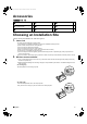
01_EN_3P191292-1E.fm Page 2 Monday, November 10, 2008 6:44 PM Accessories Indoor unit A – I A Mounting plate 1 D Insulation sheet 2 G AAA dry-cell batteries 2 B Titanium Apatite Photocatalytic Air-Purifying Filter 2 E Wireless remote controller 1 H Operation manual 1 C Drain hose 1 F Remote controller holder 1 I Installation manual 1 Choosing an Installation Site • Before choosing the installation site, obtain user approval. 1.
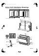
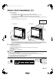
01_EN_3P191292-1E.fm Page 3 Monday, November 10, 2008 6:44 PM Indoor Unit Installation Drawings The indoor unit may be mounted in any of the three styles shown here. Exposed Half concealed Concealed A Mounting plate Molding Floor Installation Grid (Field supply) Wall Installation Location for securing the installation panel.
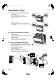
01_EN_3P191292-1E.fm Page 4 Monday, November 10, 2008 6:44 PM Installation Tips 1. Removing and installing front panel • Removal method 1) Slide until the 2 stoppers click into place. 2) Open the front panel forward and undo the string. 3) Remove the front panel. • Installation method 1) Attach the front grille and front panel after pulling the string around them. 2) Close the front panel and slide until the stoppers click outside. 2.
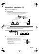
01_EN_3P191292-1E.fm Page 5 Monday, November 10, 2008 6:44 PM Indoor Unit Installation (1) Exposed installation 1. Refrigerant piping 1) 2) 3) 4) Drill a hole (65mm in diameter) in the spot indicated by the symbol in the illustration as below. The location of the hole is different depending on which side of the pipe is taken out. For piping, see 6. Connecting the refrigerant pipe, under Indoor Unit Installation (1). Allow space around the pipe for a easier indoor unit pipe connection.
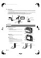
01_EN_3P191292-1E.fm Page 6 Monday, November 10, 2008 6:44 PM 3. Drain piping 1) Use commercial rigid polyvinyl chloride pipe (general VP 20 pipe, outer diameter 26mm, inner diameter 20mm) for the drain pipe. 2) The drain hose (outer diameter 18mm at connecting end, 220mm long) is supplied with the indoor unit. Prepare the drain pipe picture below position. 3) The drain pipe should be inclined downward so that water will flow smoothly without any accumulation. (Should not be trap.
01_EN_3P191292-1E.fm Page 7 Monday, November 10, 2008 6:44 PM Indoor Unit Installation (1) 4-2. Installation • Secure using 6 screws for floor installations. (Do not forget to secure to the rear wall.) • For wall installations, secure the A mounting plate using 5 screws and the indoor unit using 4 screws. • The mounting plate should be installed on a wall which can support the weight of the indoor unit.
01_EN_3P191292-1E.fm Page 8 Monday, November 10, 2008 6:44 PM 6. Connecting the refrigerant pipe CAUTION 1) Use the flare nut fixed to the main unit. (To prevent cracking of the flare nut by aged deterioration.) 2) To prevent gas leakage, apply refrigeration oil only to the inner surface of the flare. (Use refrigeration oil for R410A.) 3) Use torque wrenches when tightening the flare nuts to prevent damage to the flare nuts and gas leakage.
01_EN_3P191292-1E.fm Page 9 Monday, November 10, 2008 6:44 PM Indoor Unit Installation (1) 7. Checking for gas leakage 1) Check for leakage of gas after air purging. 2) See the sections on air purges and gas leak checks in the installation manual for the outdoor unit. Check for leakage here. • Apply soapy water and check carefully for leaking gas. • Wipe soapy water off after the check is complete. 8. Attaching the connection pipe • Attach the pipe after checking for gas leakage, described above.
01_EN_3P191292-1E.fm Page 10 Monday, November 10, 2008 6:44 PM 10.Wiring With a Multi indoor unit , install as described in the installation manual supplied with the Multi outdoor unit. • Live the sensor securing plate, remove the front metal plate cover, and connect the branch wiring to the terminal block. 1) Strip wire ends (15mm). 2) Match wire colours with terminal numbers on indoor and outdoor unit’s terminal blocks and firmly screw wires to the corresponding terminals.
01_EN_3P191292-1E.fm Page 11 Monday, November 10, 2008 6:44 PM Indoor Unit Installation (2) Half concealed installation Only items peculiar to this installation method are given here. See Exposed Installation for additional instructions. 1. Wall hole • Drill a wall hole of the size shown in the illustration on the right. 670-690 (Unit: mm) 585-595 Open size Opening hole Floor 2.
01_EN_3P191292-1E.fm Page 12 Monday, November 10, 2008 6:44 PM 4. Installing indoor unit 1) 2) 3) 4) 5) Remove the front grille. Remove 7 screws. Remove the upper casing (2 tabs). Remove the side casings (2 tabs on each side). Attach the indoor unit to the wall and secure using screws in 6 locations (M4 × 25L). Upper casing Side casing Remove 7 screws. 6 screws (M4 × 25L)(Field supply) CAUTION 1) Use drain pan edge for horizontal projection of the indoor unit.
01_EN_3P191292-1E.fm Page 13 Monday, November 10, 2008 6:44 PM Indoor Unit Installation (3) Concealed installation Only items peculiar to this installation method are given here. See Exposed Installation for additional instructions. Install the unit according to the instructions below. Failure to do so may cause lead to both cooling and heating failure and the condensation inside the house. 1) Allow enough space between the main unit and ceiling not to obstruct the flow of cool/warm air.
01_EN_3P191292-1E.fm Page 14 Monday, November 10, 2008 6:44 PM 1. Refrigerant piping Left bottom piping (Unit: mm) Right bottom piping Right/left piping 45 60 45 Hole location 75 75 45 2. Changing upward air flow dipswitch Change the upward air flow dipswitch (SW2-4) to ON to limit the upward air flow. 1) Remove the front grille. 2) Switch the dipswitch (SW2-4) on the PCB in the electrical equipment box to ON.
01_EN_3P191292-1E.fm Page 15 Monday, November 10, 2008 6:44 PM Trial Operation and Testing 1. Trial operation and testing 1-1 Measure the supply voltage and make sure that it falls in the specified range. 1-2 Trial operation should be carried out in either cooling or heating mode. ■ For Heat pump • In cooling mode, select the lowest programmable temperature; in heating mode, select the highest programmable temperature. 1) Trial operation may be disabled in either mode depending on the room temperature.
00_CV_3P191292-1E.fm Page 2 Monday, November 10, 2008 6:38 PM Two-dimensional bar code is a code for manufacturing.