
Specifications


SiENBE04-507A
vi Drawings & Flow Charts
R
radiation fin temperature rise ...............................137
remote controller
..................................................108
S
service check function ..........................................108
signal receiver PCB
...............................................41
signal transmission error
(between indoor and outdoor units)
..............118
T
target discharge pipe temperature control .............72
thermistor or related abnormality (indoor unit)
.....117
thermistor or related abnormality (outdoor unit)
...133
thermistor resistance check
.................................146
thermostat control
..................................................52
trial operation from remote controller
...................204
turning speed pulse input on the outdoor unit
PCB check
....................................................149
U
unspecified voltage
(between indoor and outdoor units)
..............119
W
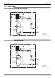
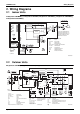
wiring diagrams
FTK(X)S20/25/35D2VMW(L)
.........................211
FTK(X)S20/25/35D3VMW(L)
.........................211
FTK(X)S20/25/35DAVMW(L)
........................211
FTK(X)S20/25/35DVMW(L)
...........................211
FTK(X)S20/25/35DVMW9
.............................211
RK(X)S20/25/35D2VMB
................................211
RK(X)S20/25/35D3VMB
................................211
RK(X)S20/25/35DVMB
..................................211