
Specifications

Indoor Unit SiENBE04-507A
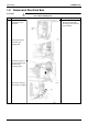
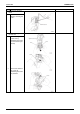
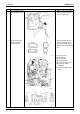
170 Removal Procedure
2
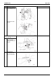
Lift up the bottom of the
control PCB and pull it
out.
When mounting the control
PCB, make sure that it is
fixed by upper hooks.
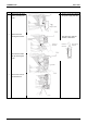
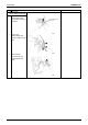
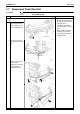
3
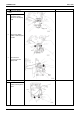
The figures show the
names of the PCB
component parts.
Lead-free solder (PbF) is
used for the PCB. When
replacing the PCB, use the
specific solder and soldering
iron.
[S1] To DC fan motor
[S6] To swing motor
[S21] HA connector
[S26] To display PCB
[S28] To signal receiver PCB
[S32] To heat exchanger
thermistor
[S35] To INTELLIGENT EYE
PCB
Step Procedure Points
Fixing
hook
Fixing hook
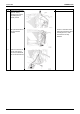
Fuse cap
Glass tube fuse
(R4288)
Varistor (w/cap)
[S1]
Fuse
(holder type
w/cap)
[S6]
[S26]
[S28]
[S32]
[S35]
[S21]
[S29]
[S27]
[S36]
SW1
RTH1
LED 1
(Green)
LED 2
(Yellow)
LED 3
(Green)