
Specifications


Instruction SiBE06-708
56 System Configuration
5
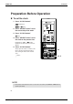
Outdoor Unit
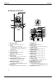
Indoor Unit
1. Titanium Apatite Photocatalytic
Air-Purifying Filter:
• These filters are attached to the inside of
the air filters.
2. Air outlet
3. Display
4. Front panel
5. Louvers (vertical blades):
(page 12.)
• The louvers are inside of the air outlet.
6. Air inlet
7. Air filter
8. Flap (horizontal blade):
(page 12.)
9. Operation lamp (green)
10. TIMER lamp (yellow): (page 17.)
11. Indoor Unit ON/OFF switch:
• Push this switch once to start operation.
Push once again to stop it.
• The operation mode refers to the following
table.
• This switch is useful when the remote
controller is missing.
12. Signal receiver:
• It receives signals from the remote
controller.
• When the unit receives a signal, you will
hear a short beep.
• Operation start ........ beep-beep
• Settings changed ..... beep
• Operation stop.......... beeeeep
13. Air outlet selection switch:
(page 13.)
14. Room temperature sensor:
•
It senses the air temperature around the unit.
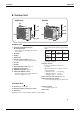
Outdoor Unit
15. Air inlet:
(Back and side)
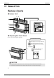
16. Refrigerant piping and inter-unit cable
17. Drain hose
18. Earth terminal:
• It is inside of this cover.
19. Air outlet
Appearance of the outdoor unit may differ from some models.
25/35 class 50 class
16
17
18
19
15
16
17
18
19
15
Model
Mode
Temperature
setting
Air flow
rate
COOLING
ONLY
COOL
22˚C AUTO
HEAT
PUMP
AUTO
25˚C
AUTO