
Specifications

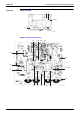

Printed Circuit Board Connector Wiring Diagram SiBE06-708
16 Printed Circuit Board Connector Wiring Diagram
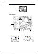
1.2.2 RK(X)S 50 F
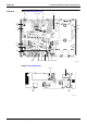
Connectors PCB(1)(Main PCB)
PCB(2)(Service Monitor PCB)
Note: Other Designations
PCB(1)(Main PCB)
PCB(2)(Service Monitor PCB)
1) S10 Connector for terminal strip (indoor-outdoor transmission)
2) S20 Connector for electronic expansion valve coil
3) S40 Connector for overload protector
4) S51, S101 Connector for service monitor PCB
5) S70 Connector for fan motor
6) S80 Connector for four way valve coil
7) S90 Connector for thermistors
(outdoor air, heat exchanger, and discharge pipe)
8) AC1, AC2 Connector for terminal strip (power supply)
9) HR1, HR2 Connector for reactor
1) S52, S102 Connector for control PCB
1) FU1 Fuse (30A)
2) FU2, FU3 Fuse (3.15A)
3) V2, V3, V5
V6, V11
Varistor
1) LED A Service monitor LED (green)
2) SW1 Forced operation ON/OFF switch