
Specifications


SiBE06-708
Drawings & Flow Charts v
Drawings & Flow Charts
A
ARC452A series .....................................................84
automatic air flow control .......................................23
automatic operation ................................................25
auto-swing ..............................................................22
C
capacitor voltage check ........................................143
check No.01 .........................................................136
check No.04 .........................................................136
check No.05 .........................................................137
check No.06 .........................................................139
check No.07 .........................................................140
check No.08 .........................................................141
check No.09 .........................................................141
check No.10 .........................................................142
check No.11 .........................................................142
check No.12 .........................................................143
check No.13 .........................................................143
check No.14 .........................................................145
check No.15 .........................................................145
compressor lock .....................................................99
compressor protection function ..............................38
compressor system sensor abnormality ...............112
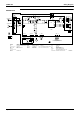
control PCB ............................................................13
control PCB (outdoor unit) ......................................15
CT or related abnormality .....................................117
D
DC fan lock ...........................................................100
DC voltage / current sensor abnormality ..............116
defrost control ........................................................41
diagnosis mode ......................................................85
discharge pipe temperature control ................38, 108
discharge pressure check ....................................141
display PCB ............................................................13
E
electrical box temperature rise .............................121
electronic expansion valve check .........................136
electronic expansion valve control .........................43
F
facility setting switch ...............................................49
fan motor (DC motor) or related abnormality .........91
fan motor connector output check ........................136
filter PCB ................................................................15
four way valve abnormality ...................................104
four way valve performance check .......................137
freeze-up protection control ...................................40
freeze-up protection control or high pressure
control .............................................................89
frequency control ....................................................33
frequency principle .................................................20
function of thermistor ..............................................31
H
heating peak-cut control ........................................ 40
high pressure control in cooling .......................... 110
I
indoor unit PCB abnormality ................................. 88
input current control .............................................. 39
input over current detection ................................. 101
installation condition check ................................. 140
insufficient gas .................................................... 129
insufficient gas control ........................................... 46
inverter features .................................................... 21
inverter POWERFUL operation ............................. 28
inverter units refrigerant system check ................ 142
J
jumper settings .................................................... 189
L
low-voltage detection .......................................... 133
M
main circuit electrolytic capacitor check .............. 145
main PCB (outdoor unit) ........................................ 17
mode hierarchy ..................................................... 32
N
night set mode ....................................................... 27
O
OL activation (compressor overload) .................... 98
ON/OFF button on indoor unit ............................... 29
operation lamp, location ........................................ 82
outdoor unit fan system check
(with DC motor) ............................................ 141
outdoor unit PCB abnormality ............................... 97
output over current detection .............................. 127
over-voltage detection ......................................... 133
P
piping diagrams
FVXS25FV1B ............................................... 192
FVXS35FV1B ............................................... 192
FVXS50FV1B ............................................... 192
RKS25F2V1B ............................................... 193
RKS35F2V1B ............................................... 193
RKS50F2V1B ............................................... 193
RXS25F2V1B ............................................... 194
RXS35F2V1B ............................................... 194
RXS50F2V1B ............................................... 194
position sensor abnormality ................................ 115
power supply waveforms check .......................... 142
power transistor check ........................................ 143
programme dry function ........................................ 24