
Specifications


SiBE06-708 Indoor Unit
Removal Procedure 157
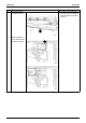
4. Removing the display
PCB.
1
Undo the 2 hooks.
2
Disconnect the
connector and remove
the display PCB.
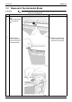
5. Removing the control
PCB.
1
Cut the cable lock belt
and pull the all Faston
terminals out from the
power terminal board.
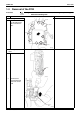
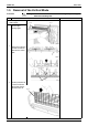
2
Disconnect each
connector.
S26:
From the service PCB
S46:
From the display PCB
S48:
From the sensor PCB
Step Procedure Points
Hooks
(R6796)
Display PCB
(R6797)
Faston
terminal
Cable lock
(R6798)
S48
S26
S46
(R6799)