
Specifications

SiBE06-708 Check
Service Diagnosis 143
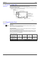
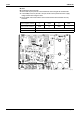
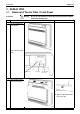
5.1.10 Capacitor Voltage Check
Check No.12 Before this checking, be sure to check the main circuit for short-circuit.
Checking the capacitor voltage
z
With the circuit breaker still on, measure the voltage according to the drawing of the model in
question. Be careful never to touch any live parts.
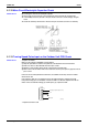
5.1.11 Power Transistor Check
Check No.13
25/35 class
Note: Check to make sure that the voltage between the terminal of Power transistor (+) and (-) is
approx. 0 volt before checking power transistor.
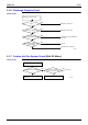
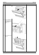
< Measuring method >
Disconnect the compressor harness connector from the outdoor unit PCB. To disengage the
connector, press the protrusion on the connector.
Then, follow the procedure below to measure resistance between power transistor (+) and (-)
and the U, V and W terminals of the compressor connector with a multi-tester. Evaluate the
measurement results for a pass/fail judgment.
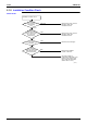
<Power transistor check>
OL lead wire
Thermistor lead wire
Fan motor lead wire
Electronic expansion valve
lead wire
Reversing solenoid
valve lead wire
(Heat pump type only)
Compressor lead wire
Reactor lead wire
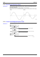
Multimeter
(DC voltage range)
(R5222)
Negative (-) terminal of
tester (positive terminal
(+) for digital tester)
Power transistor
(+)
UVW Power transistor
(-)
UVW
Positive (+) terminal of
tester (negative terminal
(-) for digital tester)
UVW Power transistor
(+)
UVW Power transistor
(-)
Normal resistance Several k
Ω
to several M
Ω
(
∗
)
Unacceptable resistance Short (0
Ω
) or open