
Service manual

SiBE06-708_C
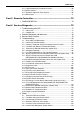
Table of Contents iv
5.7 Inverter Analyzer Check .......................................................................130
5.8 Rotation Pulse Check on the Outdoor Unit PCB ..................................131
5.9 Installation Condition Check.................................................................133
5.10 Discharge Pressure Check...................................................................133
5.11 Outdoor Fan System Check .................................................................134
5.12 Main Circuit Short Check......................................................................134
5.13 Capacitor Voltage Check......................................................................136
5.14 Power Module Check ...........................................................................137
Part 7 Trial Operation and Field Settings................................. 140
1. Pump Down Operation........................................................................141
2. Forced Cooling Operation ...................................................................142
3. Trial Operation ....................................................................................144
4. Field Settings ......................................................................................145
4.1 When 2 Units are Installed in 1 Room..................................................145
4.2 Model Type Setting ..............................................................................146
4.3 Facility Setting Jumper (cooling at low outdoor temperature) ..............146
4.4 Jumper and Switch Settings.................................................................149
5. Silicon Grease on Power Transistor / Diode Bridge............................150
Part 8 Appendix......................................................................... 151
1. Piping Diagrams..................................................................................152
1.1 Indoor Unit............................................................................................152
1.2 Outdoor Unit .........................................................................................152
2. Wiring Diagrams..................................................................................156
2.1 Indoor Unit............................................................................................156
2.2 Outdoor Unit .........................................................................................157
3. Removal Procedure (Booklet No.) ......................................................160