
Service manual

SiBE06-708_C Outdoor Unit
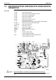
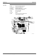
Printed Circuit Board Connector Wiring Diagram 35
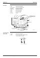
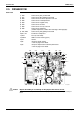
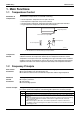
Service Monitor
PCB
SW4-A has no function. Keep it OFF.
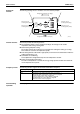
1) S52, S102 Connector for main PCB
2) LED A LED for service monitor (green)
3) SW1 Forced cooling operation ON/OFF switch
∗ Refer to page 142 for detail.
4) SW4-B
SW4-C
Switch for facility setting
∗ Refer to page 146 for detail
Switch for improvement of defrost performance
∗ Refer to page 149 for detail.
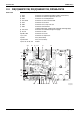
S102SW1
3P169059-1
LED A
SW4-B SW4-C
S52