
Service manual

Outdoor Unit SiBE06-708_C
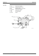
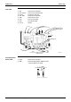
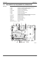
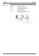
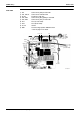
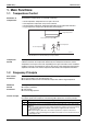
32 Printed Circuit Board Connector Wiring Diagram
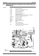
2.3 RK(X)S25/35G2V1B9, RXS25/35J2V1B, RXS25/35K2V1B,
RXS25K3V1B
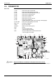
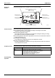
Main PCB
Caution Replace the PCB if you accidentally cut the jumpers other than J4 and J5.
Jumpers are necessary for electronic circuit. Improper operation may occur if you cut any of
them.
1) S10 Connector for filter PCB
2) S20 Connector for electronic expansion valve coil
3) S40 Connector for overload protector
4) S50 Connector for magnetic relay
5) S70 Connector for fan motor
6) S80 Connector for four way valve coil
7) S90 Connector for thermistors
(outdoor temperature, outdoor heat exchanger, discharge pipe)
8) S100 Connector for forced operation button PCB
9) HL3, HN3 Connector for filter PCB
10)HR2 Connector for reactor
11)U, V, W Connector for compressor
12)FU2 Fuse (3.15 A, 250 V)
13)LED A LED for service monitor (green)
14)V1 Varistor
15)J4 Jumper for facility setting
∗ Refer to page 146 for detail.
16)J5 Jumper for improvement of defrost performance
∗ Refer to page 149 for detail.
S10
J5 J4
S90
FU2 S100 S50
S70
S40
S20
S80
HL3
HN3
V1
LED A
UVW
HR2
2P254206-1
2P254206-11