
Service manual

SiBE06-708_C Field Settings
Trial Operation and Field Settings 145
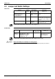
4. Field Settings
4.1 When 2 Units are Installed in 1 Room
Outline When 2 indoor units are installed in 1 room, 1 of the 2 indoor units and the corresponding
wireless remote controller can be set for different addresses.
Both the indoor unit PCB and the wireless remote controller need alteration.
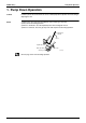
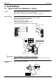
Indoor Unit PCB 1) Remove the front grille.
2) Lift the sensor PCB fixing plate and remove the front shield plate.
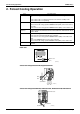
3) Disconnect the connectors [S1] [S41] [S42].
4) Remove the electric box (1 screw).
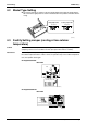
5) Pull out the indoor heat exchanger thermistor.
6) Remove the shield plate (8 tabs).
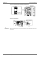
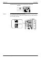
7) Cut the address setting jumper JA on the indoor unit PCB.
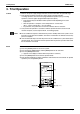
Caution Replace the PCB if you accidentally cut a wrong jumper.
Jumpers are necessary for electronic circuit. Improper operation may occur if you cut any of
them.
Wireless Remote
Controller
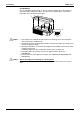
Cut the address setting jumper.
Connector [S42]
Connector [S41]
Connector [S1]
4) Remove the screw.
5) Indoor heat exchanger
thermistor
3)
6) Shield plate
(R17290)
Sensor
PCB fixing
plate
JC
JA
JB
JA
EXIST
CUT
Address
1
2
2)
Front shield
plate
Jumper
ADDRESS
(R13525)
EXIST
CUT
1
2