
Service manual

Check SiBE06-708_C
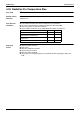
126 Service Diagnosis
5. Check
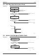
5.1 Thermistor Resistance Check
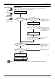
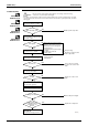
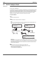
Check No.01 Disconnect the connectors of the thermistors from the PCB, and measure the resistance of
each thermistor using tester.
The data is for reference purpose only.
When the room temperature thermistor is soldered on the sensor PCB, remove the sensor
PCB from the control PCB to measure the resistance.
When the connector of indoor heat exchanger thermistor is soldered on the PCB, remove
the thermistor and measure the resistance.
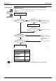
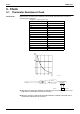
Thermistor temperature (°C) Resistance (kΩ)
–20 197.8
–15 148.2
–10 112.1
–5 85.60
065.93
551.14
10 39.99
15 31.52
20 25.02
25 20.00
30 16.10
35 13.04
40 10.62
45 8.707
50 7.176
(R25°C = 20 kΩ, B = 3950 K)
(kΩ)
150
100
50
–15 0 15 30 45
(˚C)
(R11905)
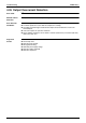
Tester
Resistance range
(R18296)
Tester
(R17417)
Room temperature
thermistor