
Service manual

Outdoor Unit SiBE061121_A
14 Printed Circuit Board Connector Wiring Diagram
2.2 RXG50K2V1B
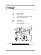
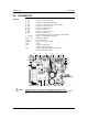
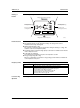
Main PCB
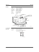
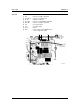
Service Monitor
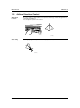
PCB
SW4-A and SW4-B have no function and keep them off.
1) S10 Connector for terminal board (indoor - outdoor transmission)
2) S20 Connector for outdoor electronic expansion valve coil
3) S40 Connector for overload protector
4) S51, S101 Connector for service monitor PCB
5) S70 Connector for fan motor
6) S80 Connector for four way valve coil
7) S90 Connector for thermistors
(outdoor temperature, outdoor heat exchanger, discharge pipe)
8) AC1, AC2 Connector for terminal board (power supply)
9) E1, E2 Connector for earth wire
10)HR1, HR2 Connector for reactor
11)U, V, W Connector for compressor
12)FU1 Fuse (30 A, 250 V)
13)FU2, FU3 Fuse (3.15 A, 250 V)
14)V2, V3, V5 V6, V11 Varistor
V3 V11
AC1
FU2E1 E2
FU3 W
2P282217-1
S40S20S80 V US70S90 S51
S10
AC2
S101
V5
V6
V2
FU1
HR1
HR2
1) S52, S102 Connector for main PCB
2) LED A LED for service monitor (green)
3) SW1 Forced cooling operation ON/OFF switch
∗ Refer to page 120 for detail.
4) SW4-C Switch for improvement of defrost performance
∗ Refer to page 126 for detail.
S102SW1
3P169059-1
LED A
SW4-C
S52