SiBE061121_A Service Manual Inverter Pair Floor Standing Type K-Series [Applied Models] O Inverter Pair : Heat Pump
SiBE061121_A Inverter Pair Floor Standing Type K-Series zHeat Pump Indoor Unit FVXG25K2V1B FVXG35K2V1B FVXG50K2V1B Outdoor Unit RXG25K2V1B RXG35K2V1B RXG50K2V1B RXG25K3V1B RXG35K3V1B RXG50K3V1B The removal procedure for each model is separately bound. Refer to page 135 for the booklet number of applicable model.
SiBE061121_A 1. Introduction .............................................................................................v 1.1 Safety Cautions ........................................................................................v 1.2 Used Icons .............................................................................................. ix Part 1 List of Functions ................................................................ 1 1. Functions...........................................................
SiBE061121_A Part 5 Remote Controller ............................................................ 53 1. FVXG25/35/50K2V1B ...........................................................................54 Part 6 Service Diagnosis............................................................. 56 1. Troubleshooting with LED .....................................................................58 1.1 Indoor Unit..............................................................................................58 1.
SiBE061121_A 5.10 5.11 5.12 5.13 5.14 Discharge Pressure Check...................................................................113 Outdoor Fan System Check .................................................................114 Main Circuit Short Check......................................................................114 Capacitor Voltage Check......................................................................115 Power Module Check .....................................................................
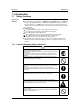
Introduction SiBE061121_A 1. Introduction 1.1 Safety Cautions Cautions and Warnings Be sure to read the following safety cautions before conducting repair work. The caution items are classified into “ Warning” and “ Caution”. The “ Warning” items are especially important since they can lead to death or serious injury if they are not followed closely. The “ Caution” items can also lead to serious accidents under some conditions if they are not followed.
SiBE061121_A Introduction Warning Be sure to wear a safety helmet, gloves, and a safety belt when working at a high place (more than 2 m). Insufficient safety measures may cause a fall accident. In case of R-410A refrigerant models, be sure to use pipes, flare nuts and tools for the exclusive use of the R-410A refrigerant. The use of materials for R-22 refrigerant models may cause a serious accident such as a damage of refrigerant cycle as well as an equipment failure.
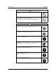
Introduction SiBE061121_A 1.1.2 Cautions Regarding Safety of Users Warning Be sure to use parts listed in the service parts list of the applicable model and appropriate tools to conduct repair work. Never attempt to modify the equipment. The use of inappropriate parts or tools may cause an electrical shock, excessive heat generation or fire. If the power cable and lead wires have scratches or deteriorated, be sure to replace them.
SiBE061121_A Introduction Warning Check to make sure that the power cable plug is not dirty or loose, then insert the plug into a power outlet securely. If the plug has dust or loose connection, it may cause an electrical shock or fire. Be sure to install the product correctly by using the provided standard For unitary type installation frame. only Incorrect use of the installation frame and improper installation may cause the equipment to fall, resulting in injury.
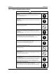
Introduction SiBE061121_A Caution Be sure to measure the insulation resistance after the repair, and make sure that the resistance is 1 MΩ or higher. Faulty insulation may cause an electrical shock. Be sure to check the drainage of the indoor unit after the repair. Faulty drainage may cause the water to enter the room and wet the furniture and floor. Do not tilt the unit when removing it. The water inside the unit may spill and wet the furniture and floor.
SiBE061121_A Part 1 List of Functions 1. Functions.................................................................................................
Functions SiBE061121_A Compressor Comfortable Airflow Comfort Control Operation Lifestyle Convenience z Operation limit for cooling (°CDB) 10 ~ 46 Operation limit for heating (°CWB) –15 ~ 18 –15 ~ 18 FVXG50K2V1B RXG50K2V1B z 10 ~ 46 Inverter (with inverter power control) FVXG25/35K2V1B RXG25/35K2V1B Basic Function Functions FVXG50K2V1B RXG50K2V1B Category FVXG25/35K2V1B RXG25/35K2V1B 1.
Compressor Comfortable Airflow Comfort Control Operation Lifestyle Convenience z z FVXG50K2V1B RXG50K3V1B Inverter (with inverter power control) FVXG25/35K2V1B RXG25/35K3V1B Basic Function Functions FVXG50K2V1B RXG50K3V1B Category Functions FVXG25/35K2V1B RXG25/35K3V1B SiBE061121_A Air-purifying filter — — Photocatalytic deodorizing filter — — Air-purifying filter with photocatalytic deodorizing function — — z z Category Health & Clean Functions Operation limit for cooling (°C
SiBE061121_A Part 2 Specifications 1. Specifications ..........................................................................................
SiBE061121_A Specifications 1. Specifications 50 Hz, 220 - 230 - 240 V Indoor Unit Model FVXG25K2V1B RXG25K2V1B Outdoor Unit Capacity Rated (Min. ~ Max.) Moisture Removal Running Current (Rated) Power Consumption Rated (Min. ~ Max.) Power Factor COP (Rated) Liquid Piping Connections Gas Drain Heat Insulation Max. Interunit Piping Length Max.
Specifications SiBE061121_A 50 Hz, 220 - 230 - 240 V Indoor Unit Model FVXG50K2V1B RXG50K2V1B Outdoor Unit Capacity Rated (Min. ~ Max.) Moisture Removal Running Current (Rated) Power Consumption Rated (Min. ~ Max.) Power Factor COP (Rated) Liquid Piping Connections Gas Drain Heat Insulation Max. Interunit Piping Length Max.
SiBE061121_A Specifications 50 Hz, 220 - 230 - 240 V Indoor Unit Model FVXG25K2V1B RXG25K3V1B Outdoor Unit Capacity Rated (Min. ~ Max.) Moisture Removal Running Current (Rated) Power Consumption Rated (Min. ~ Max.) Power Factor COP (Rated) Liquid Piping Connections Gas Drain Heat Insulation Max. Interunit Piping Length Max.
Specifications SiBE061121_A 50 Hz, 220 - 230 - 240 V Indoor Unit Model FVXG50K2V1B RXG50K3V1B Outdoor Unit Capacity Rated (Min. ~ Max.) Moisture Removal Running Current (Rated) Power Consumption Rated (Min. ~ Max.) Power Factor COP (Rated) Liquid Piping Connections Gas Drain Heat Insulation Max. Interunit Piping Length Max.
SiBE061121_A Part 3 Printed Circuit Board Connector Wiring Diagram 1. Indoor Unit.............................................................................................10 2. Outdoor Unit..........................................................................................12 2.1 25/35 Class ............................................................................................12 2.2 RXG50K2V1B ........................................................................................14 2.
Indoor Unit SiBE061121_A 1.
SiBE061121_A Indoor Unit Display PCB 1) S56 2) S1W Connector for main PCB Forced cooling operation [ON/OFF] button ∗ Refer to page 120 for detail. LED for operation (green) LED for timer (yellow) LED for RADIANT operation (red) 3) H1P 4) H2P 5) H3P S56 S1W H3P H1P H2P 3P273252-1 Service PCB 1) S27 2) S2W-1 Connector for main PCB Address setting switch ∗ Refer to page 123 for detail. S27 S2W-1 3P273254-1 SW-2, SW-3, and SW-4 have no function and keep them off.
Outdoor Unit SiBE061121_A 2. Outdoor Unit 2.
SiBE061121_A Outdoor Unit Filter PCB 1) 2) 3) 4) 5) 6) 7) 8) S11 AC1, AC2, S E1, E2 HL2, HN2 HR1 FU1 FU3 V2, V3 Connector for main PCB Connector for terminal board Terminal for earth wire Connector for main PCB Connector for reactor Fuse (3.
Outdoor Unit 2.
SiBE061121_A 2.
Outdoor Unit SiBE061121_A Filter PCB 1) 2) 3) 4) 5) 6) 7) 8) 9) S11 HL1, HN1, S E1, E2 HL2, HN2 HL4, HN4 FU1 FU3 V2, V3 SW1 Connector for [S10] on main PCB Connector for terminal board Terminal for earth wire Connector for [HL3] [HN3] on main PCB Connector for [S12] on main PCB Fuse (3.15 A, 250 V) Fuse (30 A, 250 V) Varistor Forced cooling operation ON/OFF switch ∗ Refer to page 120 for detail.
SiBE061121_A Part 4 Function and Control 1. Main Functions......................................................................................18 1.1 1.2 1.3 1.4 1.5 1.6 1.7 1.8 1.9 1.10 1.11 1.12 1.13 1.14 Temperature Control ..............................................................................18 Frequency Principle................................................................................18 Airflow Direction Control.........................................................................
Main Functions SiBE061121_A 1. Main Functions 1.1 Temperature Control Definitions of Temperatures The definitions of temperatures are classified as following.
SiBE061121_A Drawing of Inverter Main Functions The following drawing shows a schematic view of the inverter principle: Refrigerant circulation rate (high) AC power Amount of heat exchanged air (small) DC power high speed Amount of heat exchanged air (large) high f low f low speed 50 Hz freq= constant 60 Hz freq=variable Amount of heat exchanged air (large) Amount of heat exchanged air (small) capacity= variable Refrigerant circulation rate (low) Inverter Features (R2812) The inverter provid
Main Functions 1.3 SiBE061121_A Airflow Direction Control Wide-Angle Louvers The louvers, made of elastic synthetic resin, provide a wide range of airflow that guarantees a comfortable air distribution. You can adjust the position of the louvers. 45˚ (R14632) Auto-Swing 45˚ (R14633) The swinging range of the flap is the same in any operation mode.
SiBE061121_A 1.4 Main Functions Fan Speed Control for Indoor Unit Outline Phase control and fan speed control contains 9 steps: LLL, LL, SL, L, ML, M, MH, H, and HH. The airflow rate can be automatically controlled depending on the difference between the room thermistor temperature and the target temperature. This is done through phase control and Hall IC control. For more information about Hall IC, refer to the troubleshooting for fan motor on page 66.
Main Functions 1.5 SiBE061121_A RADIANT Operation The RADIANT operation has 2 operation modes. RADIANT 1: RADIANT operation with heating RADIANT 2: RADIANT operation only 1.5.1 Indoor Electronic Expansion Valve (Motor Operated Valve) Control Initializing with Power ON The indoor electronic expansion valve is initialized when turning on the power.
SiBE061121_A Main Functions 1.5.2 Indoor Unit Fan Control The movement of the indoor unit fan is different whether in RADIANT 1 or RADIANT 2. RADIANT 1 starts. Room temperature Set temperature Note: The only difference between RADIANT 1 and RADIANT 2 is the movement of the indoor unit fan. In RADIANT 1, the rotation speed of the indoor unit fan is controlled depending on the difference between the set temperature and the room temperature.
Main Functions 1.6 SiBE061121_A Program Dry Operation Outline Program dry operation removes humidity while preventing the room temperature from lowering. Since the microcomputer controls both the temperature and airflow rate, the temperature adjustment and [FAN] setting buttons are inoperable. Detail The microcomputer automatically sets the temperature and airflow rate. The difference between the room thermistor temperature at start-up and the target temperature is divided into two zones.
SiBE061121_A 1.7 Main Functions Automatic Operation Outline Detail Automatic Cooling / Heating Function When the automatic operation is selected with the remote controller, the microcomputer automatically determines the operation mode as cooling or heating according to the room temperature and the set temperature at start-up. The unit automatically switches the operation mode to maintain the room temperature at the set temperature.
Main Functions 1.8 SiBE061121_A Thermostat Control Outline Thermostat control is based on the difference between the room thermistor temperature and the target temperature. Detail Thermostat OFF Condition The temperature difference is in the zone A. Thermostat ON Condition The temperature difference returns to the zone C after being in the zone A. The system resumes from defrost control in any zones except A. The operation turns on in any zones except A.
SiBE061121_A 1.9 Main Functions NIGHT SET Mode Outline When the OFF TIMER is set, the NIGHT SET Mode is automatically activated. The NIGHT SET Mode keeps the airflow rate setting. Detail The NIGHT SET Mode continues operation at the target temperature for the first one hour, then automatically raises the target temperature slightly in the case of cooling, or lowers it slightly in the case of heating.
Main Functions SiBE061121_A 1.10 ECONO Operation Outline ECONO operation reduces the maximum operating current and the power consumption. This operation is particularly convenient for energy-saving-oriented users. It is also a major bonus for those whose breaker capacities do not allow the use of multiple electrical devices and air conditioners. It is easily activated from the wireless remote controller by pushing the [ECONO] button.
SiBE061121_A Main Functions 1.11 Inverter POWERFUL Operation Outline In order to exploit the cooling and heating capacity to full extent, operate the air conditioner by increasing the indoor fan rotating speed and the compressor frequency. Detail When the [POWERFUL] button is pressed, the fan speed and target temperature are converted to the following states for 20 minutes.
Main Functions SiBE061121_A 1.12 Clock Setting ARC466 Series The clock can be set by taking the following steps: 1. Press the [CLOCK] button. → is displayed and MON and blink. 2. Press the [SELECT] or button to set the clock to the current day of the week. 3. Press the [CLOCK] button. → blinks. 4. Press the [SELECT] or button to set the clock to the present time. Holding down the [SELECT] or button increases or decreases the time display rapidly. 5. Press the [CLOCK] button.
SiBE061121_A Main Functions 1.13 WEEKLY TIMER Operation Outline Up to 4 timer settings can be saved for each day of the week (up to 28 settings in total). The 3 items: “ON/OFF”, “temperature”, and “time” can be set. Detail Using in these cases of WEEKLY TIMER Example: The same timer settings are made for the week from Monday through Friday while different timer settings are made for the weekend. [Monday] Make timer settings up to programs 1-4.
Main Functions SiBE061121_A To use WEEKLY TIMER operation Setting mode • Make sure the day of the week and time are set. If not, set the day of the week and time. Program 1 Program 2 ON OFF Program 3 ON 8:30 17:30 6:00 OFF 27˚C 25˚C [Monday] Program 4 22:00 Setting Displays Day and number 1. Press ON/OFF Time Temperature . • The day of the week and the reservation number of the current day will be displayed. • 1 to 4 settings can be made per day. 2.
SiBE061121_A Main Functions 6. Press to select the desired time. • The time can be set between 0:00 and 23:50 in 10 minute intervals. • To return to the ON/OFF TIMER mode setting, press • Go to step 9 when setting the OFF TIMER. 7. Press . . • The time will be set. •“ ” and the temperature blink. 8. Press to select the desired temperature. • The temperature can be set between 10˚C and 32˚C. COOL or AUTO: The unit operates at 18˚C even if it is set at 10 to 17˚C.
Main Functions SiBE061121_A Copy mode • A reservation made once can be copied to another day of the week. The whole reservation of the selected day of the week will be copied. Program 1 Program 2 Program 3 ON [Monday] COPY OFF ON 8:30 17:30 25˚C 6:00 OFF 27˚C 22:00 Program 4 Program 2 Program 3 Program 1 OFF ON [Tuesday] to [Friday] Program 4 27˚C 8:30 6:00 OFF ON 25˚C 22:00 17:30 Setting Displays Copy Confirmation Paste Normal 1. Press . 2.
SiBE061121_A Main Functions Confirming a reservation • The reservation can be confirmed. Setting Displays Normal Confirmation 1. Press . • The day of the week and the reservation number of the current day will be displayed. 2. Press to select the day of the week and the reservation number to be confirmed. • Pressing displays the reservation details. • To change the confirmed reserved settings, select the reservation number and press . The mode is switched to setting mode.
Main Functions SiBE061121_A To delete reservations The individual reservation 1. Press . • The day of the week and the reservation number will be displayed. 2. Press to select the day of the week and the reservation number to be deleted. 3. Press •“ . ” and “ 4. Press • Pressing ” or “ ” blink. and select “ blank ”. changes ON/OFF TIMER mode. Pressing alternates the following items appearing on the LCD in rotational sequence. • The reservation will be no setting with selecting “blank”.
SiBE061121_A Main Functions 1.14 Other Functions 1.14.1 Hot-Start Function In order to prevent the cold air blast that normally comes when heating operation is started, the temperature of the indoor heat exchanger is detected, and the airflow is either stopped or made very weak thereby carrying out comfortable heating of the room. *The cold air blast is also prevented using similar control when the defrost control starts or when the thermostat is turned ON. 1.14.
Main Functions SiBE061121_A 1.14.6 Brightness Setting of the Indoor Unit Display Each time you press the [Brightness] button on the remote controller, the brightness of the indoor unit display changes to “high”, “low”, or “off”. Refer to the operation manual for details.
SiBE061121_A Function of Thermistor 2. Function of Thermistor Outdoor electronic expansion valve Indoor electronic expansion valve (Motor operated valve) Radiant panel (1) Four way valve (4) φ 4 (3) (4) φ 6 (2) Compressor (R14640) (1) Outdoor Heat Exchanger Thermistor 1. The outdoor heat exchanger thermistor is used for controlling the target discharge pipe temperature.
Control Specification SiBE061121_A 3. Control Specification 3.1 Mode Hierarchy Outline Air conditioner control has normal operation mode, forced operation mode, and power transistor test mode for installation and servicing.
SiBE061121_A 3.2 Control Specification Frequency Control Outline Frequency is determined according to the difference between the room thermistor temperature and the target temperature. The function is explained as follows. 1. How to determine frequency 2. Frequency command from the indoor unit (Difference between the room thermistor temperature and the target temperature) 3. Frequency initial setting 4.
Control Specification SiBE061121_A Indoor Frequency Command (∆D signal) The difference between the room thermistor temperature and the target temperature is taken as the “∆D signal” and is used for frequency command. Temperature difference ∆D signal Temperature difference ∆D signal Temperature difference ∆D signal Temperature difference ∆D signal –2.0 0 4 2.0 8 4.0 C –1.5 ∗Th OFF 1 0.5 5 2.5 9 4.5 D –1.0 –0.5 2 3 1.0 1.5 6 7 3.0 3.5 A B 5.0 5.
SiBE061121_A 3.3 Control Specification Controls at Mode Changing / Start-up 3.3.1 Preheating Control Outline The inverter operation in open phase starts with the conditions of the preheating command from the indoor unit, the outdoor temperature, and the discharge pipe temperature.
Control Specification SiBE061121_A 3.3.4 3-minute Standby Turning on the compressor is prohibited for 3 minutes after turning it off. (Except when defrosting.) 3.3.5 Compressor Protection Function When turning the compressor from OFF to ON, the upper limit of frequency is set as follows. (The function is not activated when defrosting.) (Hz) Frequency C B A D E (sec.) Time F (R13528) 3.
SiBE061121_A 3.5 Control Specification Input Current Control Outline The microcomputer calculates the input current while the compressor is running, and sets the frequency upper limit from the input current. In case of heat pump models, this control which is the upper limit control of the frequency takes priority over the lower limit of control of four way valve operation compensation.
Control Specification 3.6 SiBE061121_A Freeze-up Protection Control Outline During cooling operation, the signal sent from the indoor unit controls the operating frequency limitation and prevents freezing of the indoor heat exchanger. (The signal from the indoor unit is divided into zones.) Detail The operating frequency limitation is judged with the indoor heat exchanger temperature.
SiBE061121_A 3.8 Control Specification Outdoor Fan Control 1. Fan ON control to cool down the electrical box The outdoor fan is turned ON when the electrical box temperature is high while the compressor is OFF. 2. Fan OFF control during defrosting The outdoor fan is turned OFF during defrosting. 3. Fan OFF delay when stopped The outdoor fan is turned OFF 60 seconds after the compressor stops. 4.
Control Specification SiBE061121_A 3.10 Defrost Control Outline Defrosting is carried out by the cooling cycle (reverse cycle). The defrosting time or outdoor heat exchanger temperature must be more than a certain value to finish. Detail Conditions for Starting Defrost The starting conditions are determined with the outdoor temperature and the outdoor heat exchanger temperature. The system is in heating operation. The compressor operates for 6 minutes.
SiBE061121_A Control Specification 3.
Control Specification SiBE061121_A 3.11.1 Fully Closing with Power ON The outdoor electronic expansion valve is initialized when turning on the power. The opening position is set and the pressure equalization is developed. 3.11.2 Pressure Equalizing Control When the compressor is stopped, the pressure equalizing control is activated. The outdoor electronic expansion valve opens, and develops the pressure equalization. 3.11.
SiBE061121_A Control Specification 3.11.7 Control for Disconnection of the Discharge Pipe Thermistor Outline The disconnection of the discharge pipe thermistor is detected by comparing the discharge pipe temperature with the condensation temperature. If the discharge pipe thermistor is disconnected, the outdoor electronic expansion valve opens according to the outdoor temperature and the operation frequency, operates for a specified time, and then stops.
Control Specification SiBE061121_A 3.12 Malfunctions 3.12.1 Sensor Malfunction Detection Sensor malfunction may occur in the thermistor. Relating to Thermistor Malfunction 1. Outdoor heat exchanger thermistor 2. Discharge pipe thermistor 3. Radiation fin thermistor 4. Outdoor temperature thermistor 3.12.2 Detection of Overcurrent and Overload Outline An excessive output current is detected and the OL temperature is observed to protect the compressor.
SiBE061121_A Part 5 Remote Controller 1. FVXG25/35/50K2V1B ...........................................................................
FVXG25/35/50K2V1B SiBE061121_A 1. FVXG25/35/50K2V1B Signal transmitter Receiver Display (LCD) • Displays the current settings. (In this illustration, each section is shown with all its displays on for the purpose of explanation.) • To use the remote controller, aim the transmitter at the indoor unit. If there is anything to block signals between the unit and the remote controller, such as a curtain, the unit will not operate. • The maximum distance for communication is approx. 7m.
SiBE061121_A FVXG25/35/50K2V1B Open the Front Cover MODE button • Selects the operation mode. ECONO3 button • ECONO operation. QUIET button SWING4 button • OUTDOOR UNIT QUIET operation. • Adjusts the airflow direction. • When you press the SWING button, the flap moves up and down. The flap stops when you press the SWING button again. • QUIET operation is not available in FAN and DRY operation. • QUIET operation and POWERFUL operation cannot be used at the same time.
SiBE061121_A Part 6 Service Diagnosis 1. Troubleshooting with LED .....................................................................58 1.1 Indoor Unit..............................................................................................58 1.2 Outdoor Unit ...........................................................................................58 2. Problem Symptoms and Measures .......................................................59 3. Service Check Function ................................
SiBE061121_A 5.9 5.10 5.11 5.12 5.13 5.14 Service Diagnosis Installation Condition Check.................................................................113 Discharge Pressure Check...................................................................113 Outdoor Fan System Check .................................................................114 Main Circuit Short Check......................................................................114 Capacitor Voltage Check..........................................
Troubleshooting with LED SiBE061121_A 1. Troubleshooting with LED 1.1 Indoor Unit Operation Lamp The operation lamp blinks when any of the following errors is detected. 1. When a protection device of the indoor or outdoor unit is activated, or when the thermistor malfunctions. 2. When a signal transmission error occurs between the indoor and outdoor units. In either case, conduct the diagnostic procedure described in the following pages. Operation lamp (green) (R14646) Service Monitor 1.
SiBE061121_A Problem Symptoms and Measures 2. Problem Symptoms and Measures Symptom Check Item The unit does not operate. Check the power supply. Check the type of the indoor unit. Check the outdoor temperature. Diagnose with remote controller indication. Operation sometimes stops. Details of Measure Reference Page Check if the rated voltage is supplied. Check if the indoor unit type is compatible with the outdoor unit.
Service Check Function SiBE061121_A 3. Service Check Function Check Method 1 1. When the timer cancel button is held down for 5 seconds, 00 is displayed on the temperature display screen. Timer cancel button (R14553) < ARC466 Series > 2. Press the timer cancel button repeatedly until a long beep sounds. The code indication changes in the sequence shown below. Note: 60 No. Code No. Code No.
SiBE061121_A Service Check Function Check Method 2 1. Press the center of the [Temp] button and the [Mode] button at the same time. (R11669) 5C is displayed on the LCD. (R11821) 2. Select 5C (service check) with the [Temp] or button. 3. Press the [Mode] button to enter the service check mode. (R11672) The left-side number blinks. (R11670) 4. Press the [Temp] or button and change the number until you hear the two consecutive beeps or the long beep.
Service Check Function SiBE061121_A 5. Diagnose by the sound. beep : The left-side number does not correspond with the error code. two consecutive beeps : The left-side number corresponds with the error code but the right-side number does not. long beep : Both the left-side and right-side numbers correspond with the error code. (The numbers indicated when you hear the long beep are the error code. → Refer to page 63.) 6. Press the [Mode] button. (R11672) The right-side number blinks. (R11673) 7.
SiBE061121_A Troubleshooting 4. Troubleshooting 4.
Troubleshooting 4.2 SiBE061121_A Indoor Unit PCB Abnormality A1 Error Code Method of Error Detection The system checks if the circuit works properly within the microcomputer of the indoor unit. Error Decision Conditions The system cannot set the internal settings.
SiBE061121_A 4.3 Troubleshooting Freeze-up Protection Control or Heating Peak-cut Control Error Code A5 Method of Error Detection Freeze-up protection control Error Decision Conditions Freeze-up protection control During cooling operation, the freeze-up protection control (operation halt) is activated according to the temperature detected by the indoor heat exchanger thermistor.
Troubleshooting 4.4 SiBE061121_A Fan Motor (DC Motor) or Related Abnormality Error Code A6 Method of Error Detection The rotation speed detected by the Hall IC during fan motor operation is used to determine abnormal fan motor operation. Error Decision Conditions The detected rotation speed does not reach the demanded rotation speed of the target tap, and is less than 50% of the maximum fan motor rotation speed.
SiBE061121_A Troubleshooting Troubleshooting Caution Check No.02 Refer to P.107 Be sure to turn off the power switch before connecting or disconnecting connectors, or parts may be damaged. Turn off the power supply and rotate the fan by hand. Does the fan rotate smoothly? NO Replace the indoor fan motor. YES Turn the power on and start operation. Does the fan rotate? Turn off the power supply NO and disconnect the fan motor connector, then turn the power on.
Troubleshooting 4.5 SiBE061121_A Radiant Panel Temperature Rise, Indoor Electronic Expansion Valve (Motor Operated Valve) Abnormality, Freeze-up Protection Control Error Code Method of Error Detection A9 Radiant panel temperature rise During RADIANT operation, high temperature control (e.g., operation halt, indoor electronic expansion valve closure) is activated according to the temperature detected by the radiant panel thermistors.
SiBE061121_A Troubleshooting Troubleshooting Be sure to turn off the power switch before connecting or disconnecting connectors, or parts may be damaged. Caution Check No.01 Refer to P.106 Check No.12 Refer to P.108 Check the operation condition. Condition OK? YES Check No. 12 Check the indoor electronic expansion valve coil. OK? ∗ When the outdoor temperature is below the lower limit for cooling operation (10˚C), the freeze-up protection control is activated and the cooling operation stops.
Troubleshooting 4.6 SiBE061121_A Thermistor or Related Abnormality (Indoor Unit) Error Code C4, C9, CE Method of Error Detection The temperatures detected by the thermistors determine thermistor errors. Error Decision Conditions The thermistor input is more than 4.96 V or less than 0.04 V during compressor operation. Supposed Causes Disconnection of connector Defective thermistor Defective indoor unit PCB Troubleshooting Caution Check No.01 Refer to P.
SiBE061121_A 4.7 Troubleshooting Refrigerant Shortage Error Code Method of Error Detection U0 Refrigerant shortage detection I: Refrigerant shortage is detected by checking the input current value and the compressor running frequency. If the refrigerant is short, the input current is lower than the normal value. Refrigerant shortage detection II: Refrigerant shortage is detected by checking the discharge pipe temperature and the opening of the outdoor electronic expansion valve.
Troubleshooting SiBE061121_A Refrigerant shortage detection III: (25/35 class only) When the difference of the temperature is smaller than K°C, it is regarded as refrigerant shortage. Operation mode Description Cooling room thermistor temperature – indoor heat exchanger temperature outdoor heat exchanger temperature – outdoor temperature 4.0 4.0 Heating indoor heat exchanger temperature – room thermistor temperature outdoor temperature – outdoor heat exchanger temperature 3.0 3.
SiBE061121_A Troubleshooting Troubleshooting Caution Check No.01 Refer to P.106 Check No.12 Refer to P.108 Be sure to turn off the power switch before connecting or disconnecting connectors, or parts may be damaged. Any thermistor disconnected? NO Stop valve closed? YES Replace the thermistor(s) in ∗ Discharge pipe thermistor position. ∗ Indoor or outdoor heat exchanger thermistor ∗ Room temperature thermistor ∗ Outdoor temperature thermistor YES Open the stop valve.
Troubleshooting 4.8 SiBE061121_A Low-voltage Detection or Over-voltage Detection Error Code U2 Indoor Unit Method of Error Detection The zero-cross detection of the power supply is evaluated by the indoor unit PCB. Outdoor Unit Low-voltage detection: An abnormal voltage drop is detected by the DC voltage detection circuit. Over-voltage detection: An abnormal voltage rise is detected by the over-voltage detection circuit.
SiBE061121_A Troubleshooting Troubleshooting Caution Be sure to turn off the power switch before connecting or disconnecting connectors, or parts may be damaged. Check the power supply voltage. Voltage as rated? NO Correct the power supply. YES Check the connection of the compressor harness. Loose or disconnected? YES Reconnect the harness. NO Does the outdoor fan rotate smoothly? NO Replace both the fan motor and the outdoor unit PCB.
Troubleshooting 4.9 SiBE061121_A Signal Transmission Error (between Indoor Unit and Outdoor Unit) Error Code U4 Method of Error Detection The data received from the outdoor unit in signal transmission is checked whether it is normal. Error Decision Conditions The data sent from the outdoor unit cannot be received normally, or the content of the data is abnormal.
SiBE061121_A Troubleshooting Troubleshooting Caution Check No.11 Refer to P.107 Be sure to turn off the power switch before connecting or disconnecting connectors, or parts may be damaged. Check the power supply voltage. Voltage as rated? NO Correct the power supply. YES Check the indoor unit - outdoor unit connection wires. Is there any wiring error? YES Correct the indoor unit outdoor unit connection wires. NO Check the voltage of the connection wires on the indoor terminal board between No.
Troubleshooting SiBE061121_A 4.10 Signal Transmission Error on Outdoor Unit PCB (RXG50K2V1B Only) Error Code U7 Method of Error Detection Communication error between microcomputer mounted on the main microcomputer and PM1. Error Decision Conditions The abnormality is determined when the data sent from the PM1 can not be received for 9 seconds. The error counter is reset when the data from the PM1 can be successfully received.
SiBE061121_A Troubleshooting 4.11 Unspecified Voltage (between Indoor Unit and Outdoor Unit) Error Code UA Method of Error Detection The supply power is detected for its requirements (different from pair type and multi type) by the indoor / outdoor transmission signal. Error Decision Conditions The pair type and multi type are interconnected.
Troubleshooting SiBE061121_A 4.12 Outdoor Unit PCB Abnormality Error Code E1 Method of Error Detection The system checks if the microprocessor is working in order. The system checks if the zero-cross signal comes in properly. Error Decision Conditions The microprocessor program runs out of control. The zero-cross signal is not detected.
SiBE061121_A Troubleshooting Troubleshooting RXG50K2V1B Caution Be sure to turn off the power switch before connecting or disconnecting connectors, or parts may be damaged. Turn on the power again. Error again? YES Replace the outdoor unit PCB. NO Check to see if the unit is grounded. Grounded? YES NO Ground the system. The cause can be external factors other than malfunction. Investigate the cause of noise.
Troubleshooting SiBE061121_A 4.13 OL Activation (Compressor Overload) Error Code E5 Method of Error Detection A compressor overload is detected through compressor OL. Error Decision Conditions If the error repeats, the system is shut down.
SiBE061121_A Troubleshooting Troubleshooting Caution Check No.01 Refer to P.106 Check No.12 Refer to P.108 Check No.13 Refer to P.109 Be sure to turn off the power switch before connecting or disconnecting connectors, or parts may be damaged. Discharge pipe thermistor disconnected? Insert the thermistor in position. NO Check No. 01 Check the thermistors. NG ∗ Discharge pipe thermistor Replace the discharge pipe thermistor. OK Connectors are properly connected? Check No.14 Refer to P.
Troubleshooting SiBE061121_A 4.14 Compressor Lock Error Code E6 Method of Error Detection A compressor lock is detected by checking the compressor running condition through the position detection circuit. Error Decision Conditions 25/35 class Operation stops due to overcurrent. If the error repeats, the system is shut down.
SiBE061121_A Troubleshooting 4.15 DC Fan Lock Error Code E7 Method of Error Detection An error is determined with the high-voltage fan motor rotation speed detected by the Hall IC. Error Decision Conditions The fan does not start in about 15 ~ 30 seconds even when the fan motor is running. If the error repeats, the system is shut down.
Troubleshooting SiBE061121_A 4.16 Input Overcurrent Detection Error Code E8 Method of Error Detection An input overcurrent is detected by checking the input current value with the compressor running. Error Decision Conditions The current exceeds about 9.25 ~ 20 A (depending on the model) for 2.5 seconds with the compressor running. (The upper limit of the current decreases when the outdoor temperature exceeds a certain level.
SiBE061121_A Troubleshooting 4.17 Four Way Valve Abnormality Error Code EA Method of Error Detection The room temperature thermistor and the indoor heat exchanger thermistor are checked if they function within their normal ranges in each operation mode. Error Decision Conditions A following condition continues over 1 ~ 10 minutes (depending on the model) after operating for 5 ~ 10 minutes (depending on the model). Cooling / Dry (room thermistor temp. – indoor heat exchanger temp.
Troubleshooting SiBE061121_A Troubleshooting Caution Check No.01 Refer to P.106 Be sure to turn off the power switch before connecting or disconnecting connectors, or parts may be damaged. Four way valve coil disconnected (loose)? YES Correct the four way valve coil. NO Check No.13 Refer to P.109 Harness out of connector? YES Reconnect the harness. NO Check No.14 Refer to P.109 Check the continuity of the four way valve coil and harness. Disconnect the harness from the connector.
SiBE061121_A Troubleshooting 4.18 Discharge Pipe Temperature Control Error Code F3 Method of Error Detection An error is determined with the temperature detected by the discharge pipe thermistor. Error Decision Conditions If the temperature detected by the discharge pipe thermistor rises above A°C, the compressor stops. The error is cleared when the discharge pipe temperature has dropped below B°C.
Troubleshooting SiBE061121_A 4.19 High Pressure Control in Cooling Error Code F6 Method of Error Detection High-pressure control (operation halt, frequency drop, etc.) is activated in cooling operation if the temperature sensed by the outdoor heat exchanger thermistor exceeds the limit. Error Decision Conditions The temperature sensed by the outdoor heat exchanger thermistor rises above about 60 ~ 65°C (depending on the model). The error is cleared when the temperature drops below about 50°C.
SiBE061121_A Troubleshooting 4.20 Compressor System Sensor Abnormality 4.20.1 25/35 Class, RXG50K3V1B Error Code H0 Method of Error Detection The system checks the DC current before the compressor starts. Error Decision Conditions The DC current before compressor start-up is out of the range 0.5 ~ 4.5 V (sensor output converted to voltage value) The DC voltage before compressor start-up is below 50 V.
Troubleshooting SiBE061121_A 4.20.2 RXG50K2V1B Error Code Method of Error Detection H0 The system checks the power supply voltage and the DC voltage before the compressor starts. The system checks the compressor current right after the compressor starts. Error Decision Conditions The power supply voltage and the DC voltage is obviously low or high. The compressor current does not run when the compressor starts.
SiBE061121_A Troubleshooting 4.21 Position Sensor Abnormality Error Code H6 Method of Error Detection A compressor start-up failure is detected by checking the compressor running condition through the position detection circuit. Error Decision Conditions If the error repeats, the system is shut down.
Troubleshooting Troubleshooting Check No.15 Refer to P.110 Check No.18 Refer to P.113 Check No.20 Refer to P.114 SiBE061121_A 25/35 class, RXG50K3V1B Caution Be sure to turn off the power switch before connecting or disconnecting connectors, or parts may be damaged. Turn off the power. Check the power supply voltage. Voltage as rated? NO Correct the power supply. YES Check No. 18 Check the discharge pressure. OK? NO Replace the stop valve. YES Check No.
SiBE061121_A Troubleshooting Check No.15 Refer to P.110 Check No.18 Refer to P.113 Troubleshooting RXG50K2V1B Caution Be sure to turn off the power switch before connecting or disconnecting connectors, or parts may be damaged. Turn off the power. Check the power supply voltage. Voltage as rated? NO Correct the power supply. YES Check No. 18 Check the discharge pressure. OK? NO Replace the stop valve. YES Check the connection.
Troubleshooting SiBE061121_A 4.22 DC Voltage / Current Sensor Abnormality (25/35 Class Only) Error Code H8 Method of Error Detection DC voltage or DC current sensor abnormality is identified based on the compressor running frequency and the input current. Error Decision Conditions If the error repeats, the system is shut down.
SiBE061121_A Troubleshooting 4.23 CT or Related Abnormality (RXG50K2V1B Only) Error Code H8 Method of Error Detection A CT or related error is detected by checking the compressor running frequency and CTdetected input current. Error Decision Conditions The compressor running frequency is more than A Hz, and the CT input current is less than B A. A (Hz) 55 B (A) 0.5 If the error repeats, the system is shut down.
Troubleshooting SiBE061121_A Troubleshooting Check No.15 Refer to P.110 Check No.21 Refer to P.115 Caution Be sure to turn off the power switch before connecting or disconnecting connectors, or parts may be damaged. Turn off the power and turn it on again. Start operation. ∗ Running current as shown at right with relay cable 1 or 2? YES Current (guideline) Replace the outdoor unit PCB.
SiBE061121_A Troubleshooting 4.24 Thermistor or Related Abnormality (Outdoor Unit) Error Code H9, J3, J6, P4 Method of Error Detection This fault is identified based on the thermistor input voltage to the microcomputer. A thermistor fault is identified based on the temperature sensed by each thermistor. Error Decision Conditions The thermistor input voltage is above 4.96 V or below 0.04 V with the power on.
Troubleshooting Troubleshooting SiBE061121_A In case of “H9” “J3” “J6” Caution Check No.01 Refer to P.106 Be sure to turn off the power switch before connecting or disconnecting connectors, or parts may be damaged. Turn on the power again. Error displayed again on remote controller? NO Reconnect the connectors or thermistors. YES Check No. 01 Check the thermistor resistance value. Normal? J3 error: the discharge pipe temperature is lower than the heat exchanger temperature.
SiBE061121_A Troubleshooting 4.25 Electrical Box Temperature Rise Error Code L3 Method of Error Detection An electrical box temperature rise is detected by checking the radiation fin thermistor with the compressor off. Error Decision Conditions With the compressor off, the radiation fin temperature is above A°C. The error is cleared when the radiation fin temperature drops below B°C.
Troubleshooting SiBE061121_A 4.26 Radiation Fin Temperature Rise Error Code L4 Method of Error Detection A radiation fin temperature rise is detected by checking the radiation fin thermistor with the compressor on. Error Decision Conditions Supposed Causes 102 If the radiation fin temperature with the compressor on is above A°C. The error is cleared when the radiation fin temperature drops below B°C. If the error repeats, the system is shut down.
SiBE061121_A Troubleshooting Troubleshooting Caution Check No.17 Refer to P.113 Be sure to turn off the power switch before connecting or disconnecting connectors, or parts may be damaged. Turn off the power and turn it on again to start the system. Check No.19 Refer to P.114 YES Error displayed again? Has the PCB been replaced? NO YES NO Check if silicon grease is applied properly on the radiation fin. If not, apply the silicon grease. Check the radiation fin temperature.
Troubleshooting SiBE061121_A 4.27 Output Overcurrent Detection Error Code L5 Method of Error Detection An output overcurrent is detected by checking the current that flows in the inverter DC section. Error Decision Conditions A position signal error occurs while the compressor is running. A speed error occurs while the compressor is running. An output overcurrent signal is fed from the output overcurrent detection circuit to the microcomputer. If the error repeats, the system is shut down.
SiBE061121_A Troubleshooting Troubleshooting Caution Check No.15 Refer to P.110 Check No.17 Refer to P.113 Be sure to turn off the power switch before connecting or disconnecting connectors, or parts may be damaged. ∗ An output overcurrent may result from wrong internal wiring. If the system is interrupted by an output overcurrent after the wires have been disconnected and reconnected for part replacement, check the wiring again. Check No. 17 Check the installation condition.
Check SiBE061121_A 5. Check 5.1 Thermistor Resistance Check Check No.01 Disconnect the connectors of the thermistors from the PCB, and measure the resistance of each thermistor using tester. The relationship between normal temperature and resistance is shown in the table and the graph below. The data is for reference purpose only. Thermistor temperature (°C) –20 Resistance (kΩ) 197.8 –15 –10 148.2 112.1 –5 0 85.60 65.93 5 10 51.14 39.99 15 20 31.52 25.02 25 20.00 30 35 16.10 13.
SiBE061121_A 5.2 Check Fan Motor Connector Output Check Check No.02 1. 2. 3. 4. 5. Check the connection of connector. Check the motor power supply voltage output (pins 4 - 7). Check the motor control voltage (pins 4 - 3). Check the rotation command voltage (pins 4 - 2). Check the rotation pulse (pins 4 - 1). S1 7 6 5 4 3 2 1 Motor power supply voltage (310 ~ 340 VDC) Unused Unused GND Motor control voltage (15 VDC) Rotation command voltage (1~ 5 VDC) Rotation pulse input (R12404) 5.
Check 5.4 SiBE061121_A Electronic Expansion Valve Check Check No.12 Conduct the followings to check the electronic expansion valve (EV). 1. Check to see if the EV connector is correctly connected to the PCB. 2. Turn the power off and on again, and check to see if the EV generates a latching sound. 3. If the EV does not generate a latching sound in the above step 2, disconnect the connector and check the continuity using a tester. 4. Check the continuity between the pins 1 - 6, 2 - 6, 3 - 6, and 4 - 6.
SiBE061121_A 5.5 Check Four Way Valve Performance Check Check No.13 Turn the power off and then on again. Start heating operation. S80 voltage at 220 - 240 VAC with compressor on? (Fig. 1) ∗ Four way valve coil Cooling / Dry : No continuity Heating : Continuity NO Replace the outdoor unit PCB. YES Disconnect the four way valve coil from the connector and check the continuity. Four way valve coil resistance at 1000 ~ 2000 Ω? NO Replace the four way valve coil. YES Replace the four way valve.
Check 5.7 SiBE061121_A Inverter Analyzer Check Check No.15 Characteristics Inverter analyzer: RSUK0917C If an abnormal stop occurs due to compressor startup failure or overcurrent output when using an inverter unit, it is difficult to judge whether the stop is caused by the compressor failure or some other failure (main PCB, power module, etc.). The inverter analyzer makes it possible to judge the cause of trouble easily and securely.
SiBE061121_A Check Diagnose method (Diagnose according to 6 LEDs lighting status.) (1) If all the LEDs are lit uniformly, the compressor is defective. → Replace the compressor. (2) If the LEDs are not lit uniformly, check the power module. → Refer to Check No.22. (3) If NG in Check No.22, replace the power module. (Replace the main PCB. The power module is united with the main PCB.) If OK in Check No.22, check if there is any solder cracking on the PCB.
Check 5.8 SiBE061121_A Rotation Pulse Check on the Outdoor Unit PCB Check No.16 25/35 class 1. Check that the voltage between the pins 10 - 11 is 15 VDC. 2. Check if the Hall IC generates the rotation pulse (0 ~ 15 VDC) 4 times between the pins 10 12, 10 - 13, when the fan motor is manually rotated once.
SiBE061121_A 5.9 Check Installation Condition Check Check No.17 Installation condition check Check the allowable dimensions of the air suction and discharge area. NG Change the installation location or direction. OK Is the discharged air short-circuited? YES Change the installation location or direction. NO Is the outdoor heat exchanger very dirty? YES Clean the outdoor heat exchanger.
Check SiBE061121_A 5.11 Outdoor Fan System Check Check No.19 DC motor Check the outdoor fan system. Fan motor lead wire connector disconnected? NO Outdoor fan running? YES YES Reconnect the connector. NO Go to Check No. 16. Outdoor fan system is functioning. (R15001) 5.12 Main Circuit Short Check Check No.20 25/35 class, RXG50K3V1B only Note: Check to make sure that the voltage between (+) and (–) of the diode bridge (DB1) is approx. 0 V before checking.
SiBE061121_A Check RXG50K3V1B 4 3 2 1 – ~ ~ + – + Tester (R14700) 5.13 Capacitor Voltage Check Check No.21 RXG50K2V1B only Before this check, be sure to check the main circuit for short circuit. With the circuit breaker still on, measure the voltage according to the drawing of the model in question. Be careful never to touch any live parts.
Check SiBE061121_A 5.14 Power Module Check Check No.22 Note: Check to make sure that the voltage between (+) and (–) of the power module is approx. 0 V before checking. Disconnect the compressor harness connector from the outdoor unit PCB. To disengage the connector, press the protrusion on the connector. Follow the procedure below to measure resistance between the terminals of the power module and the terminals of the compressor with a multi-tester.
SiBE061121_A Check RXG50K2V1B Power module (R16073) RXG50K3V1B Power module (R16692) Service Diagnosis 117
SiBE061121_A Part 7 Trial Operation and Field Settings 1. 2. 3. 4. Pump Down Operation........................................................................119 Forced Cooling Operation ...................................................................120 Trial Operation ....................................................................................122 Field Settings ......................................................................................123 4.1 4.2 4.3 4.
SiBE061121_A Pump Down Operation 1. Pump Down Operation Outline In order to protect the environment, be sure to conduct pump down operation when relocating or disposing the unit. Detail 1) Remove the valve caps from the liquid stop valve and the gas stop valve. 2) Carry out forced cooling operation. 3) After 5 to 10 minutes, close the liquid stop valve with a hexagonal wrench. 4) After 2 to 3 minutes, close the gas stop valve and stop the forced cooling operation.
Forced Cooling Operation SiBE061121_A 2. Forced Cooling Operation Item Conditions Forced Cooling The forced cooling operation is allowed when both the following conditions are met. 1) The outdoor unit is not abnormal and not in the 3-minute standby mode. 2) The outdoor unit is not operating. Start Command frequency End Others The forced cooling operation starts when any of the following conditions is fulfilled.
SiBE061121_A Forced Cooling Operation Outdoor Unit (RXG50K2V1B) S102 S2 ON A B CD LED-A SW4 Forced cooling operation ON/OFF switch SW1 (R14963) Outdoor Unit (RXG50K3V1B) Forced cooling operation ON/OFF switch (SW1) 1 2 3 Push Screwdriver Caution (R18725) When pressing the switch, do not touch the terminal board. It has a high voltage and may cause electric shock.
Trial Operation SiBE061121_A 3. Trial Operation Outline 1. Measure the power supply voltage and make sure that it falls within the specified range. 2. Trial operation should be carried out in either cooling or heating operation. 3. Carry out the trial operation in accordance with the operation manual to ensure that all functions and parts, such as flap movement, are working properly. The air conditioner requires a small amount of power in standby mode.
SiBE061121_A Field Settings 4. Field Settings 4.1 When 2 Units are Installed in 1 Room Outline When 2 indoor units are installed in 1 room, 1 of the 2 indoor units and the corresponding wireless remote controller can be set for different addresses. Both the indoor unit PCB and the wireless remote controller need alteration. Indoor Unit PCB (1) Remove the front panel, air filters and front grille. (2) Remove the screw, and remove the service cover.
Field Settings 4.2 SiBE061121_A Standby Electricity Saving Outline 25/35 Class Only This function turns OFF the power supply to the outdoor unit and sets the indoor unit into standby electricity saving mode, thus reducing the power consumption of the air conditioner. Detail The standby electricity saving function is turned OFF before shipping. The following procedure is required for turning ON the function. 1. Check that the main power supply is turned OFF. Turn OFF if it has not been turned OFF. 2.
SiBE061121_A 4.3 Field Settings Facility Setting Jumper (cooling at low outdoor temperature) Outline RXG50K3V1B only This function is limited only for facilities (the target of air conditioning is equipment (such as computer)). Never use it in a residence or office (the space where there is a human). Detail You can expand the operation range to –10°C by cutting jumper J6 on the outdoor unit PCB. If the outdoor temperature falls to –18°C or lower, the operation stops.
Field Settings 4.4 SiBE061121_A Jumper and Switch Settings Indoor Unit Function Jumper Fan speed setting when compressor stops for thermostat OFF. (effective only in cooling operation) Power failure recovery function JB When connected (factory set) Fan speed setting; Remote controller setting JC Auto-restart When cut Fan speed setting; “0” (The fan stops.) The unit does not resume operation after recovering from a power failure. Timer settings are cleared.
SiBE061121_A Silicon Grease on Power Transistor / Diode Bridge 5. Silicon Grease on Power Transistor / Diode Bridge Outline Apply the specified silicon grease to the heat radiation part of a power transistor / diode bridge when you replace an outdoor unit PCB. The silicon grease encourages the heat radiation of a power transistor / diode bridge. Detail 1. 2. 3. 4. Wipe off the old silicon grease completely. Apply the silicon grease evenly. See the illustrations below for examples of application.
SiBE061121_A Part 8 Appendix 1. Piping Diagrams..................................................................................129 1.1 Indoor Unit............................................................................................129 1.2 Outdoor Unit .........................................................................................130 2. Wiring Diagrams..................................................................................132 2.1 Indoor Unit.....................................
SiBE061121_A Piping Diagrams 1. Piping Diagrams Indoor Unit FVXG25/35K2V1B FVXG50K2V1B INDOOR UNIT INDOOR UNIT THERMISTOR ON HEAT EXCH. CROSS FLOW FAN FIELD PIPING 6.4CuT FIELD PIPING 9.5CuT THERMISTOR ON HEAT EXCH. CROSS FLOW FAN FIELD PIPING 6.4CuT M FAN MOTOR FIELD PIPING 12.7CuT 9.5CuT REFRIGERANT FLOW COOLING HEATING M FAN MOTOR 9.5CuT REFRIGERANT FLOW COOLING HEATING 4D071597 Appendix THERMISTOR HEAT EXCHANGER 6.4CuT HEAT EXCHANGER 6.4CuT MV THERMISTOR RADIANT PANEL 6.
Piping Diagrams 1.2 SiBE061121_A Outdoor Unit RXG25/35K2V1B, RXG25/35K3V1B OUTDOOR UNIT OUTDOOR TEMPERATURE THERMISTOR 9.5CuT 7.0CuT HEAT EXCHANGER 7.0CuT 4.8CuT MUFFLER WITH FILTER M ELECTRONIC EXPANSION VALVE EV φ.4.0×ID. 2.0CuT HEAT EXCHANGER THERMISTOR 4.8CuT 6.4CuT 6.4CuT MUFFLER WITH FILTER 9.5CuT PROPELLER FAN 9.5CuT FOUR WAY VALVE ON: HEATING 9.5CuT 7.9CuT 6.4CuT MUFFLER WITH FILTER FIELD PIPING LIQUID STOP (6.4CuT) VALVE MUFFLER 7.9CuT DISCHARGE PIPE THERMISTOR 9.
SiBE061121_A Piping Diagrams RXG50K3V1B OUTDOOR UNIT HEAT EXCHANGER 7.9CuT OUTDOOR TEMPERATURE THERMISTOR 7.9CuT 7.9CuT 7.9CuT 7.9CuT CAPILLARY TUBE 1 7.9CuT 4.0CuT 7.9CuT 7.9CuT 4.0CuT 7.9CuT 7.9CuT CAPILLARY TUBE 2 CAPILLARY TUBE 3 4.0CuT HEAT EXCHANGER THERMISTOR 4.0CuT CAPILLARY TUBE 4 EV M MUFFLER WITH FILTER 6.4CuT PROPELLER FAN 7.9CuT MUFFLER 7.9CuT DISCHARGE PIPE THERMISTOR COMPRESSOR RECEIVER MUFFLER 6.4CuT 9.5CuT MUFFLER ELECTRONIC EXPANSION VALVE 6.4CuT 9.5CuT 12.7CuT 12.
Wiring Diagrams SiBE061121_A 2. Wiring Diagrams 2.1 Indoor Unit FVXG25/35/50K2V1B S27 1 PCB3 S2W(4) 3 SIGNAL RECEIVER H1P H2P M M RED ORG YLW BLK BLU 9 S30 1 S21 6 1 S34 5 3 S331 1 S32 S35 BLK BLK 2 1 t˚ R4T F1U H1P~H3P M1F M1S PCB1~PCB3 R1T~R4T : : : : : : : t˚ M M1F t˚ R2T t˚ 5 Z1C outdoor CAUTION NOTE THAT OPERATION WILL RESTART AUTOMATICALLY IF THE MAIN POWER SUPPLY IS TURNED OFF AND THEN BACK ON AGAIN. RED 4 BLU BRN ORG WHT 1 HA → FIELD WIRING.
SiBE061121_A 2.2 Wiring Diagrams Outdoor Unit RXG25/35K2V1B, RXG25/35K3V1B FIELD WIRING.
Wiring Diagrams SiBE061121_A RXG50K3V1B FIELD WIRING indoor TO INDOOR UNIT POWER SUPPLY outdoor NOTE 1.REFER TO THE NAMEPLATE FOR THE POWER REQUIREMENTS.
SiBE061121_A Removal Procedure (Booklet No.) 3. Removal Procedure (Booklet No.) Refer to the following booklets for removal procedure. Appendix ∗FVXG25/35/50K2V1B Refer to Si061263. ∗RXG25/35K2V1B Refer to Si001156. ∗RXG25/35K3V1B Refer to Si001273. ∗RXG50K2V1B Refer to Si001164. ∗RXG50K3V1B Refer to Si001274.
Revision History Month / Year Version 07 / 2011 SiBE061121 12 / 2012 SiBE061121_A Revised contents First edition Model addition: RXG25/35/50K3V1B
Warning z Daikin products are manufactured for export to numerous countries throughout the world. Prior to purchase, please confirm with your local authorised importer, distributor and/or retailer whether this product conforms to the applicable standards, and is suitable for use, in the region where the product will be used. This statement does not purport to exclude, restrict or modify the application of any local legislation. z Ask a qualified installer or contractor to install this product.