Français Deutsch English FVXG25K2V1B FVXG35K2V1B FVXG50K2V1B 00_CV_3P276870-1.
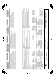
FVXG25K2V1B, FVXG35K2V1B, FVXG50K2V1B DAIKIN INDUSTRIES, LTD. , , Shinri Sada Manager Quality Control Department Low Voltage 2006/95/EC Electromagnetic Compatibility 2004/108/EC * Umeda Center Bldg., 2-4-12, Nakazaki-Nishi, Kita-ku, Osaka, 530-8323 Japan 74736-KRQ/EMC97-4957 KEMA Quality B.V. DAIKIN.TCF.015 N9/01-2011 3SB64417-15P.
FVXG25K2V1B, FVXG35K2V1B, FVXG50K2V1B , , Shinri Sada Manager Quality Control Department Umeda Center Bldg., 2-4-12, Nakazaki-Nishi, Kita-ku, Osaka, 530-8323 Japan 3SB64417-16L.
3SB64417-16L.
Safety Precautions • The precautions described herein are classified as WARNING and CAUTION. They both contain important information regarding safety. Be sure to observe all precautions without fail. • Meaning of WARNING and CAUTION notices WARNING ....Failure to follow these instructions properly may result in personal injury or loss of life. CAUTION .....Failure to observe these instructions properly may result in property damage or personal injury, which may be serious depending on the circumstances.
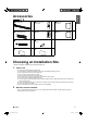
Indoor unit English Accessories A – K A Mounting plate E Wireless remote controller 1 B Titanium apatite photocatalytic air-purifying filter J Operation manual 1 F Remote controller holder 2 C Drain hose 1 K Installation manual 1 1 G Dry battery AAA. LR03 (alkaline) 1 D Insulation sheet (1) 2 H Insulation sheet (2) 2 1 Choosing an Installation Site • Before choosing the installation site, obtain user approval. 1.
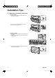
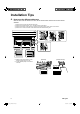
Installation Tips 1. Removing and installing front panel • Removal method 1) Slide the front panel stoppers on both sides upward, and open the front panel. Front panel stopper Upward 2) Remove the strings on both sides from the hooks. 3) Lift the front panel to remove it. • Installation method 1) Hang the hooks (3 positions) on the lower section of the front panel. 2) Hang the strings on both sides on the hooks, and close the front panel.
Removing and installing air filters English 2. Air filter (upper) • Removal method 1) Open the front panel. 2) Remove both air filters (upper). 3) Remove both air filters (lower). Air filter (lower) 2) Pull down 3) Pull up 1) Open • Installation method Using the reverse order from the installation, install the air filters (lower), and then install the air filters (upper). 3. Removing and installing front grille • Removal method 1) Remove the front panel and air filters.
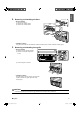
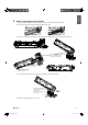
Installation Tips 4. How to set the different addresses When two indoor units are installed in one room, the two wireless remote controllers can be set for different addresses. 1) 2) 3) 4) Remove the front panel, air filters and front grille. Remove the service lid screw (1 pc.), and then remove the service lid. Remove the harness for the fan motor connection and harness for the motor valve coil connection. Remove the 3 screws, and take out the terminal block and electrical wiring box.
English 5. When connecting to an HA system 1) Take out the terminal block and electrical wiring box, and open the lid for the electrical wiring box. 2) Remove the 2 screws, and open the lid for the electrical wiring box. 3) Attach the connection cord to the S21 connector and pull the harness out through the notched part in the figure. 3)-1. Remove a fixing screw. Tab 3)-2. Remove the tabs (3 positions), and detach the terminal block. Be careful the connection cord is not caught. S21 3)-3.
Indoor Unit Installation Patterns • The indoor unit can not be installed at a position where it directly comes in contact with the floor. • There are two installation patterns shown below as a standard installation specification of the indoor unit. • Be sure to install the indoor unit on a wall that can bear the weight of the unit adequately for any installation pattern. Exposed installation Half concealed installation • For half concealed installation, please refer to page 20 and 21.
English Indoor Unit Installation Drawings • Be sure to install the indoor unit in accordance with the installation instructions below for any installation pattern. Install the indoor unit where there is no obstacle above the unit. Obstacles affect the air current distribution, and an adequate heating or cooling effect cannot be obtained.
Indoor Unit Installation Exposed installation 1. Installing the mounting plate • Decide the installation site with reference to the descriptions on pages 2, 7, and 8. • Before choosing the installation site, obtain user approval. • The mounting plate should be installed on a wall which can support the weight of the indoor unit. 1) Temporarily secure the mounting plate to the wall, make sure that the panel is completely level, and mark the boring points on the wall.
English 2. Refrigerant piping • • • • Create a hole in the refrigerant piping in accordance with the conditions shown in the illustration. The location of the hole is different depending on which side of the pipe is taken out. Allow space around the pipe for an easier indoor unit pipe connection. Maintain an adequate working length for the refrigerant pipe starting from the reference point, as shown in the illustration.
Indoor Unit Installation 4. Shaping the refrigerant pipe • Form the shape of the refrigerant pipe in accordance with the restrictions shown in the illustration. • Protect the open end of the pipe against dust and moisture. Wall Be sure to place a cap. Rain If no flare cap is available, cover the flare mouth with tape to keep dirt or water out. Piping pull-out dimensions Left back piping Right back piping 320 36.
English 5. Installing the indoor unit on the mounting plate 1) Remove the front panel and front grille. 2) Insert the C drain hose into the socket of the drain pan. Fully insert the drain hose until it adheres to a seal of the socket. Drain pan Seal C Drain hose C Drain hose For side piping • Before performing the side piping work, remove the pipe port cover on the side the pipe is routed. 1) Open the screw covers on both sides of the air outlet cover using a flathead screwdriver.
Indoor Unit Installation 5) Open the flap. 6) Remove the air outlet cover. 6)-2. Remove the air outlet cover while pulling the 5 tabs inside the air outlet cover. 6)-1. Remove the air outlet cover while lifting the 3 tabs on the upper radiant panel. 13 01_EN_3P276870-1.
English 7) Remove the fixing screws (2 pcs.), press the tabs (3 positions) using a flathead screwdriver, and remove the upper casing. 8) Remove the fixing screw (1 pc.) of both side, press the tabs (2 positions) using a flathead screwdriver, and remove the side casing on the pipe port cover removing side for the piping. 9) Remove the pipe port cover for the piping with reference to the slit. Frame Casing Remove the pipe port cover.
Indoor Unit Installation Connecting the drain hose to the VP pipe, and hanging the indoor unit on the mounting plate 1) Use commercial rigid polyvinyl chloride pipe (general VP 20 pipe, outer diameter 26mm, inner diameter 20mm) for the drain pipe. 2) The drain hose (outer diameter 18mm at connecting end, 220mm long) is supplied with the indoor unit. Prepare the drain pipe picture below position. 3) The drain pipe should be inclined downward so that water will flow smoothly without any accumulation.
1. English Refrigerant Piping Work Removing the drip proof cover • Take out 1 screw and remove the drip proof cover. Tab Hook • Use the holding tape attached to the unit to temporarily fix the drip proof cover to the side of the unit. 2. Flaring the pipe end 1) Cut the pipe end with a pipe cutter. 2) Remove burrs with the cut surface facing downward so that the chips do not enter the pipe. 3) Put the flare nut on the pipe. 4) Flare the pipe. 5) Check that the flaring is properly made.
Refrigerant Piping Work 3. Refrigerant piping CAUTION • Use the flare nut fixed to the main unit. (To prevent cracking of the flare nut by aged deterioration.) • To prevent gas leakage, apply refrigeration oil only to the inner surface of the flare. (Use refrigeration oil for R410A.) • Use torque wrenches when tightening the flare nuts to prevent damage to the flare nuts and gas leakage. Align the centres of both flares and tighten the flare nuts 3 or 4 turns by hand.
English 4. Purging air • For the air purging procedures, please refer to the outdoor unit’s installation manual. 5. Checking for gas leakage • When the refrigerant piping connection is complete, check the air purge and gas leakage. • Check for any gas leakage from the section connected to the radiant panel that is connected at the time of shipping. 6.
Wiring 1) Open the service lid. 2) Strip wire ends (15mm). 3) Match wire colours with terminal numbers on indoor and outdoor unit’s terminal blocks and firmly screw wires to the corresponding terminals. 4) Connect the earth wires to the corresponding terminals. 5) Pull wires to make sure that they are securely latched up, then retain wires with wire retainer. 6) Shape the wires so that the service lid fits securely, then close service lid. Firmly fix the wires with the terminal screws.
English Half Concealed Installation Only items peculiar to this installation method are given here. See Exposed Installation for additional instructions. 1. Opening a wall hole for half concealed installation • Drill a wall hole of the size shown in the illustration. (unit: mm) 865-885 570-580 Open size 70-120 Opening hole Floor 2. Installation of supplemental plate for attaching the unit • The rear of the unit can be fixed with screws at the supplemental plate shown in the illustration.
Half Concealed Installation 3. Refrigerant piping • Refer to Shaping the refrigerant pipe (page 11) for details. (unit: mm) Wall Hole location Right bottom piping Right/left piping 40 40 Left bottom piping 45 Wall 105 105 40 4. Floor Installing indoor unit 1) Remove front panel, air filters, front grille, air outlet cover, and three casings. 2) Attach the indoor unit to the wall and secure using screws in 4 locations.
1. English Trial Operation and Testing Trial operation and testing 1-1 Measure the supply voltage and make sure that it falls in the specified range. 1-2 For trial operation, make sure to perform either COOL or HEAT operation, and RADIANT operation. • In cooling mode, select the lowest programmable temperature; in heating mode, select the highest programmable temperature. 1) Trial operation may be disabled in either mode depending on the room temperature.
Two-dimensional bar code is a code for manufacturing. 3P276870-1 M10B206 00_CV_3P276870-1.