SiBE01 - 503 SPLIT Pair D-Series [Applied Models] zNon-Inverter Pair : Heat Pump
SiBE01-503 Non Inverter Pair D-Series zHeat Pump Indoor Unit FTYN25DV3B ATY20DV2 FTYN35DV3B ATY25DV2 ATY35DV2 Outdoor Unit RYN25DV3B RYN35DV3B Table of Contents ARY20DV2 ARY25DV2 ARY35DV2 i
SiBE01-503 1. Introduction .............................................................................................v 1.1 Safety Cautions ........................................................................................v Part 1 List of Function .................................................................. 1 1. Functions.................................................................................................2 Part 2 Specifications ...................................................
SiBE01-503 Part 6 Service Diagnosis............................................................. 51 1. 2. 3. 4. Caution for Diagnosis............................................................................52 Problem Symptoms and Measures .......................................................53 Service Check Function ........................................................................54 Troubleshooting ....................................................................................57 4.1 4.
SiBE01-503 Index ............................................................................................. i Drawings & Flow Charts ...............................................................
SiBE01-503 Introduction 1. Introduction 1.1 Safety Cautions Cautions and Warnings Be sure to read the following safety cautions before conducting repair work. Warning” and “ Caution”. The “ The caution items are classified into “ Warning” items are especially important since they can lead to death or serious injury if they are not followed closely. The “ Caution” items can also lead to serious accidents under some conditions if they are not followed.
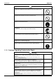
Introduction SiBE01-503 Caution Do not repair the electrical components with wet hands. Working on the equipment with wet hands can cause an electrical shock. Do not clean the air conditioner by splashing water. Washing the unit with water can cause an electrical shock. Be sure to provide the grounding when repairing the equipment in a humid or wet place, to avoid electrical shocks. Be sure to turn off the power switch and unplug the power cable when cleaning the equipment.
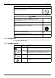
SiBE01-503 Introduction Warning Be sure to use the specified cable to connect between the indoor and outdoor units. Make the connections securely and route the cable properly so that there is no force pulling the cable at the connection terminals. Improper connections can cause excessive heat generation or fire. When connecting the cable between the indoor and outdoor units, make sure that the terminal cover does not lift off or dismount because of the cable.
Introduction SiBE01-503 Warning Do not use a joined power cable or extension cable, or share the same power outlet with other electrical appliances, since it can cause an electrical shock, excessive heat generation or fire. Caution Check to see if the parts and wires are mounted and connected properly, and if the connections at the soldered or crimped terminals are secure. Improper installation and connections can cause excessive heat generation, fire or an electrical shock.
SiBE01-503 Part 1 List of Function 1. Functions.................................................................................................
Functions SiBE01-503 Functions Inverter (with Inverter Power Control) Comfortable Airflow Comfort Control Operation Lifestyle Convenience — Air Purifying Filter with Bacteriostatic, Virustatic Functions — 15 ~46 Photocatalytic Deodorizing Filter — Operation Limit for Heating (°CWB) –10 ~15 Air Purifying Filter with Photocatalytic Deodorizing Function — Titanium Apatite Photocatalytic Air-Purifying Filter { Longlife Filter — { PAM Control — Oval Scroll Compressor — Swing Compressor
Functions Inverter (with Inverter Power Control) Basic Function Compressor Comfortable Airflow Comfort Control Operation Lifestyle Convenience Operation Limit for Cooling (°CDB) Operation Limit for Heating (°CWB) –10 ~15 — Oval Scroll Compressor — Swing Compressor — Health & Clean Air Purifying Filter with Bacteriostatic, Virustatic Functions — Photocatalytic Deodorizing Filter — Air Purifying Filter with Photocatalytic Deodorizing Function — Titanium Apatite Photocatalytic Air-Purifyin
Functions 4 SiBE01-503 List of Function
SiBE01-503 Part 2 Specifications 1. Specifications ..........................................................................................
Specifications SiBE01-503 1. Specifications 50Hz 230V Indoor Units Models FTYN25DV3B RYN25DV3B Outdoor Units Capacity Rated (Min.~Max.) Moisture Removal Running Current (Rated) Power Consumption Rated (Min.~Max.
SiBE01-503 Specifications 50Hz 220V Indoor Units Models ATY20DV2 ARY20DV2 Outdoor Units Capacity Moisture Removal Running Current Power Consumption Power Factor COP Liquid Piping Connections Gas Drain Heat Insulation Indoor Units Front Panel Color Air Flow Rate m³/min (cfm) Type Motor Output Speed Air Direction Control Air Filter Running Current Power Consumption Power Factor Temperature Control Dimensions (H×W×D) Packaged Dimensions (H×W×D) Weight Gross Weight Operation H/M/L Sound Outdoor Units Casin
Specifications SiBE01-503 50Hz 220V Indoor Units Models ATY35DV2 ARY35DV2 Outdoor Units Capacity Moisture Removal Running Current Power Consumption Power Factor COP Liquid Piping Connections Gas Drain Heat Insulation Indoor Units Front Panel Color Air Flow Rate m³/min (cfm) Type Motor Output Speed Air Direction Control Air Filter Running Current Power Consumption Power Factor Temperature Control Dimensions (H×W×D) Packaged Dimensions (H×W×D) Weight Gross Weight Operation H/M/L Sound Outdoor Units Casin
SiBE01-503 Part 3 Printed Circuit Board Connector Wiring Diagram 1. Printed Circuit Board Connector Wiring Diagram..................................10 1.1 Indoor Unit..............................................................................................
Printed Circuit Board Connector Wiring Diagram SiBE01-503 1. Printed Circuit Board Connector Wiring Diagram 1.
SiBE01-503 Printed Circuit Board Connector Wiring Diagram Control PCB FU1 H1 V1 S2 H2 S1 V2 H3 S4 H4 S5 H5 S7 S6 S33 S27 LED A J30 JC JA S32 (R4670) Signal Receiver PCB LED1 LED2 S26 RTH SW1 (R4671) Printed Circuit Board Connector Wiring Diagram 11
Printed Circuit Board Connector Wiring Diagram 12 SiBE01-503 Printed Circuit Board Connector Wiring Diagram
SiBE01-503 Part 4 Functions and Control 1. Functions...............................................................................................14 1.1 1.2 1.3 1.4 1.5 1.6 1.7 1.8 Power-Airflow Dual Flaps, Wide-Angle Louvers and Auto-Swing ..........14 Fan Speed Control for Indoor Units........................................................15 Thermostat Control.................................................................................16 Automatic Operation.........................................
Functions SiBE01-503 1. Functions 1.1 Power-Airflow Dual Flaps, Wide-Angle Louvers and Auto-Swing Power-Airflow Dual Flaps The large flaps send a large volume of air downwards to the floor. The flap provides an optimum control area in cooling, heating and dry mode. Heating Mode During heating mode, the large flap enables direct warm air straight downwards. The flap presses the warm air above the floor to reach the entire room. Cooling Mode During cooling mode, the flap retracts into the indoor unit.
SiBE01-503 1.2 Functions Fan Speed Control for Indoor Units Control Mode The air flow rate can be automatically controlled depending on the difference between the set temperature and the room temperature. This is done through phase control and Hall IC control. For more information about Hall IC, refer to troubleshooting for fan motor on page 61. Phase Steps Phase control and fan speed control contains 7 steps:LL, L, LM, M, HM, H, and HH.
Functions 1.3 SiBE01-503 Thermostat Control Thermostat control is based on the difference between the room temperature and the setpoint.
SiBE01-503 1.4 Functions Automatic Operation Outline When the automatic mode is selected with the remote controller, the microcomputer determines the operation mode from cooling and heating according to the room temperature and the setpoint. The unit automatically switches the operation mode to cooling or heating to maintain the room temperature.
Functions 1.5 SiBE01-503 Programme Dry Function Outline Programme dry function removes humidity while preventing the room temperature from lowering. Since the microcomputer controls both the temperature and air flow rate, the temperature adjustment and fan adjustment buttons are inoperable in this mode. Details of the Control The microcomputer automatically sets the target temperature and fan setting (L tap). Target temperature is determined as follows.
SiBE01-503 1.6 Functions Night Set Mode When the OFF timer is set, the Night Set circuit automatically activates. The Night Set circuit maintains the airflow setting made by users. The Night Set Circuit The Night Set circuit continues heating or cooling the room at the set temperature for the first one hour, then automatically lowers the temperature setting slightly in the case of heating, or raises it slightly in the case of cooling, for economical operations.
Functions 1.7 SiBE01-503 POWERFUL Operation Outline In order to exploit the cooling and heating capacity to full extent, operate the air conditioner by increasing the indoor fan rotating speed. Details of the Control When POWERFUL button is pushed, the fan speed and the target temperature will be converted to the following states for 20 minutes. Operation mode Cooling Heating Fan speed HH tap HH tap Target temperature 18°C 30°C Ex.) : POWERFUL operation in cooling mode. Target temp. Set temp.
SiBE01-503 1.8 Functions Other Functions 1.8.1 Hot Start Function In order to prevent the cold draft that normally comes when heating operation starts, the temperature of the indoor heat exchanger is detected, and either the air flow is stopped or is made very weak thereby carrying out comfortable heating of the room. *The cold draft is also prevented using a similar control when the thermostat turns OFF. 1.8.
Function of Thermistor SiBE01-503 2. Function of Thermistor A B Four way valve Compressor (R4733) A Outdoor Heat Exchanger Thermistor (DCB) 1. The outdoor heat exchanger thermistor is used for high pressure control during cooling operation. B Indoor Heat Exchanger Thermistor (DCN) 1. The indoor heat exchanger thermistor is used to prevent freezing. During the cooling operation, if the temperature drops abnormally, the operating frequency becomes lower, then the operation must be halted.
SiBE01-503 Control Specification 3. Control Specification 3.1 Four Way Valve Switching Outline Current is conducted during heating operation, and current is not conducted during cooling or defrosting. In order to eliminate the switching sound (as the four way valve coil switches from ON to OFF) when the heating is stopped, the delay switch of the four way valve is carried out after the operation stopped. Detail The four way valve is switched 2 minutes after the compressor stops. 3.
Control Specification 3.6 Outline Detail SiBE01-503 Heating Peak-cut Control During heating operation, heating peak-cut control is activated according to the temperature of the indoor heat exchanger to prevent abnormal high pressure. Conditions for starting Temperature of the indoor heat exchanger ≥ 63°C (FTYN models), 65°C (ATY models) While controlling The compressor halts. The outdoor fan switches ON/OFF according to the temperature of the indoor heat exchanger.
SiBE01-503 3.8 Control Specification Defrost Control Outline In heating, defrosting is carried out by the cooling cycle (reverse cycle) to prevent the outdoor heat exchanger being frosted. The defrosting time or outdoor heat exchanger temperature must be more than its fixed value when finishing. Detail Time chart for 35 class Heating Defrosting Heating 86sec. Compressor 86sec. ON OFF 73sec. Four way valve Outdoor unit fan Indoor unit fan 73sec.
Control Specification 26 SiBE01-503 Functions and Control
SiBE01-503 Part 5 System Configuration 1. System Configuration............................................................................28 2. Instructions............................................................................................29 2.1 2.2 2.3 2.4 2.5 2.6 2.7 2.8 2.9 System Configuration Safety Precautions .................................................................................29 Names of Parts....................................................................................
System Configuration SiBE01-503 1. System Configuration After the installation and test operation of the room air conditioner have been completed, it should be operated and handled as described below. Every user would like to know the correct method of operation of the room air conditioner, to check if it is capable of cooling (or heating) well, and to know a clever method of using it.
SiBE01-503 Instructions 2. Instructions Note: 2.1 This instruction is for FTYN models as representative. Safety Precautions Safety precautions • • • • Keep this manual where the operator can easily find them. Read this manual attentively before starting up the unit. For safety reason the operator must read the following cautions carefully. This manual classifies precautions into WARNING and CAUTION. Be sure to follow all precautions below: they are all important for ensuring safety.
Instructions SiBE01-503 • Do not stand or sit on the outdoor unit. Do not place any object on the unit to avoid injury, do not remove the fan guard. • Do not place anything under the indoor or outdoor unit that must be kept away from moisture. In certain conditions, moisture in the air may condense and drip. • After a long use, check the unit stand and fittings for damage. • Do not touch the air inlet and aluminum fins of outdoor unit. It may cause injury.
SiBE01-503 2.
Instructions SiBE01-503 Outdoor Unit 15 17 18 19 16 Indoor Unit 1. Air filter 2. Titanium Apatite Photocatalytic Air-Purifying Filter: • These filters are attached to the inside of the air filters. 3. Air inlet 4. Front panel 5. Panel tab 6. Room temperature sensor: • It senses the air temperature around the unit. 7. Display 8. Air outlet 9. Flaps (horizontal blades): (page 12.) 10. Louvres (vertical blades): • The louvers are inside of the air outlet. (page 12.) 11.
SiBE01-503 Instructions Remote Controller 1 2 4 5 3 6 7 8 10 9 11 < ARC445A1 > 1. Signal transmitter: • It sends signals to the indoor unit. 2. Display: • It displays the current settings. (In this illustration, each section is shown with all its displays ON for the purpose of explanation.) 3. POWERFUL button: POWERFUL operation (page 13.) 4. ON/OFF button: • Press this button once to start operation. Press once again to stop it. • The button glows even in dark rooms. 6.
Instructions 2.3 SiBE01-503 Preparation before Operation Preparation Before Operation To set the batteries 1 1. Pull the tabs on top down and open the lid. 2. Set two dry batteries (AAA). 3. Insert the two tabs in the bottom of the lid and close the lid as it was before. Top tab 3 2 Lower tabs (2 places) ATTENTION About batteries • When replacing the batteries, use batteries of the same type, and replace the two old batteries together.
SiBE01-503 Instructions Preparation Before Operation To operate the remote controller • To use the remote controller, aim the transmitter at the indoor unit. If there is anything to block signals between the unit and the remote controller, such as a curtain, the unit will not operate. • Do not drop the remote controller. Do not get it wet. • The maximum distance for communication is about 7 m. Receiver To fix the remote controller holder on the wall 1.
Instructions SiBE01-503 Turn the breaker ON • Turning ON the breaker opens the flap, then closes it again. (This is a normal procedure.) NOTE Tips for saving energy • Be careful not to cool (heat) the room too much. Recommended temperature setting Keeping the temperature setting at a moderate level helps save energy. • Cover windows with a blind or a curtain. For cooling:26°C – 28°C Blocking sunlight and air from outdoors increases the cooling (heating) For heating:20°C – 24°C effect.
SiBE01-503 2.4 Instructions AUTO • DRY • COOL • HEAT • FAN Operation AUTO · DRY · COOL · HEAT · FAN Operation The air conditioner operates with the operation mode of your choice. From the next time on, the air conditioner will operate with the same operation mode. To start operation 1. Press “MODE selector button” and select a operation mode. 2,3 1 • Each pressing of the button advances the mode setting in sequence. : AUTO 4 : DRY 5 : COOL : HEAT : FAN 2. Press “ON/OFF button” .
Instructions SiBE01-503 To change the air flow rate setting 5. Press “FAN setting button”. DRY mode AUTO or COOL or HEAT or FAN mode Three levels of air flow rate setting from “ The air flow rate setting is not variable. plus “ ” to “ ” ” are available. Settings using the indoor unit operation switches The main body operation switch should only be used in emergencies when the remote control is lost or broken, its battery has run out, or it is otherwise unusable.
SiBE01-503 2.5 Instructions Adjusting the Air Flow Direction Adjusting the Air Flow Direction You can adjust the air flow direction to increase your comfort. To adjust the horizontal blades (flaps) 1. Press “SWING button”. The display will light up and the flaps will begin to swing. 2. When the flaps have reached the desired position, press “SWING button” once more. 1,2 The display will go blank. The flaps will stop moving.
Instructions 2.6 SiBE01-503 POWERFUL Operation POWERFUL Operation POWERFUL operation quickly maximizes the cooling (heating) effect. You can get the maximum capacity. ■ To start POWERFUL operation 1. Press “POWERFUL button”. • POWERFUL operation ends in 20 minutes. Then the system automatically operates again with the settings which were used before POWERFUL operation. • When using POWERFUL operation, there are some functions which are not available. • “ ” is displayed on the LCD.
SiBE01-503 2.7 Instructions TIMER Operation TIMER Operation Timer functions are useful for automatically switching the air conditioner on or off at night or in the morning. You can also use OFF TIMER and ON TIMER in combination. ■ To use OFF TIMER operation 1. Press “OFF TIMER button”. ON OFF The TIMER lamp lights up. • The time changes in 1 hour increments every time the button is pushed, with a maximum of 9 hours. 2 1 ■ To cancel the OFF TIMER operation 2. Press “CANCEL button”.
Instructions SiBE01-503 ■ To use ON TIMER operation 1. Press “ON TIMER button”. The TIMER lamp lights up. ON OFF • The time changes in 1 hour increments every time the button is pushed, with a maximum of 12 hours. 2 1 ■ To cancel ON TIMER operation 2. Press “CANCEL button”. • The TIMER lamp goes off. ■ To combine ON TIMER and OFF TIMER • A sample setting for combining the two timers is shown below. Display (Example) The air conditioner is currently operating.
SiBE01-503 2.8 Instructions Care and Cleaning Care and Cleaning CAUTION Before cleaning, be sure to stop the operation and turn the breaker OFF. Units ■ Indoor unit, Outdoor unit and Remote controller 1. Wipe them with dry soft cloth. ■ Front panel 1. Open the front panel. • Hold the panel by the tabs on the two sides and lift it unitl it stops with a click. 2. Remove the front panel. • Supporting the front panel with one hand, release the lock by sliding down the knob with the other hand.
Instructions SiBE01-503 Filters 1. Open the front panel. (page 16.) 2. Pull out the air filters. • Push a little upwards the tab at the center of each air filter, then pull it down. 3. Take off the Titanium Apatite Photocatalytic Air-Purifying Filter. Titanium Apatite Photocatalytic Air-Purifying Filter Air filter • Hold the recessed parts of the frame and unhook the four claws. 4. Clean or replace each filter. See below. 5.
SiBE01-503 Instructions Check Check that the base, stand and other fittings of the outdoor unit are not decayed or corroded. Check that nothing blocks the air inlets and the outlets of the indoor unit and the outdoor unit. Check that the drain comes smoothly out of the drain hose during COOL or DRY operation. • If no drain water is seen, water may be leaking from the indoor unit. Stop operation and consult the service shop if this is the case. ■ Before a long idle period 1.
Instructions 2.9 SiBE01-503 Troubleshooting Trouble Shooting These cases are not troubles. The following cases are not air conditioner troubles but have some reasons. You may just continue using it. Case Explanation Operation does not start soon. • When ON/OFF button was pressed soon after operation was stopped. • When the mode was reselected. • This is to protect the air conditioner. You should wait for about 3 to 4 minutes. Hot air does not flow out soon after the start of heating operation.
SiBE01-503 Instructions Check again. Please check again before calling a repair person. Case The air conditioner does not operate. (OPERATION lamp is off.) Check • Hasn’t a breaker turned OFF or a fuse blown? • Isn’t it a power failure? • Are batteries set in the remote controller? • Is the timer setting correct? Cooling (Heating) effect is poor.
Instructions SiBE01-503 Call the service shop immediately. WARNING ■ When an abnormality (such as a burning smell) occurs, stop operation and turn the breaker OFF. Continued operation in an abnormal condition may result in troubles, electric shocks or fire. Consult the service shop where you bought the air conditioner. ■ Do not attempt to repair or modify the air conditioner by yourself. Incorrect work may result in electric shocks or fire. Consult the service shop where you bought the air conditioner.
SiBE01-503 Instructions Fault diagnosis. FAULT DIAGNOSIS BY REMOTE CONTROLLER In the ARC445A series, the temperature display sections on the main unit indicate corresponding codes. 1. When the TIMER CANCEL button is held down for 5 seconds, a “ ” indication flashes on the temperature display section. TIMER CANCEL button It cancels the timer setting. 2. Press the TIMER CANCEL button repeatedly until a continuous beep is produced.
Instructions 50 SiBE01-503 System Configuration
SiBE01-5033 Part 6 Service Diagnosis 1. 2. 3. 4. Caution for Diagnosis............................................................................52 Problem Symptoms and Measures .......................................................53 Service Check Function ........................................................................54 Troubleshooting ....................................................................................57 4.1 4.2 4.3 4.4 4.5 4.6 4.7 Error Codes and Description ...............
Caution for Diagnosis SiBE01-503 1. Caution for Diagnosis The operation lamp flashes when any of the following errors is detected. 1. When a protection device of the indoor or outdoor unit is activated or when the thermistor malfunctions, disabling equipment operation. 2. When a signal transmission error occurs between the indoor and outdoor units. In either case, conduct the diagnostic procedure described in the following pages.
SiBE01-503 Problem Symptoms and Measures 2. Problem Symptoms and Measures Problem Check None of the units operates. Check the power supply. Check the type of the indoor units. Check the outdoor air temperature. Diagnosis with remote controller indication Check the remote controller addresses. Operation sometimes stops. Check the power supply. Check the outdoor air temperature. Equipment operates but does not cool, or does not heat.
Service Check Function SiBE01-503 3. Service Check Function The temperature display sections on the main unit indicate corresponding codes. Check Method 1 1. When the timer cancel button is held down for 5 seconds, a “00” indication flashes on the temperature display section. TIMER CANCEL button It cancels the timer setting. (R4759) 2. Press the timer cancel button repeatedly until a continuous beep is produced. The code indication changes in the sequence shown below, and notifies with a long beep.
SiBE01-503 Service Check Function Check Method 2 1. Enter the diagnosis mode. Press the 3 buttons (TEMP ,TEMP , MODE) simultaneously. (R4735) The digit of the number of tens blinks. Try again from the start when the digit does not blink. (R4736) 2. Press the TEMP button. Press TEMP or TEMP and change the digit until you hear the sound of “beep” or “pi pi”. (R4737) 3. Diagnose by the sound. “ pi ” : The number of tens does not accord with the error code.
Service Check Function SiBE01-503 The digit of the number of units blinks. (R4739) 5. Press the TEMP button. Press TEMP or TEMP and change the digit until you hear the sound of “beep”. (R4737) 6. Diagnose by the sound. “ pi ” : The both numbers of tens and units do not accord with the error code. “ pi pi ” : The number of tens accords with the error code. “ beep ” : The both numbers of tens and units accord with the error code. 7. Determine the error code.
SiBE01-503 Troubleshooting 4. Troubleshooting 4.
Troubleshooting 4.2 SiBE01-503 Indoor Unit PCB Abnormality A1 Remote Controller Display Method of Malfunction Detection Evaluation of zero-cross detection of power supply by indoor unit. Malfunction Decision Conditions When there is no zero-cross detection in approximately 1.25 continuous seconds. Supposed Causes Faulty indoor unit PCB Faulty connector connection Troubleshooting Caution Be sure to turn off power switch before connect or disconnect connector, or parts damage may be occurred.
SiBE01-503 4.3 Troubleshooting Freeze-up Protection Control or High Pressure Control Remote Controller Display A5 Method of Malfunction Detection High pressure control Malfunction Decision Conditions High pressure control Supposed Causes Service Diagnosis During heating operations, the temperature detected by the indoor heat exchanger thermistor is used for the high pressure control (stop, outdoor fan stop, etc.
Troubleshooting SiBE01-503 Troubleshooting Caution Check No.06 Refer to P.67 Be sure to turn off power switch before connect or disconnect connector, or parts damage may be occurred. Check the air passage. Is there any short-circuit? YES Provide sufficient air passage. NO Check the intake air filter. Is it very dirty? YES Clean the air filter. NO Check the dust accumulation on the indoor unit heat exchanger. Is it very dirty? YES Clean the heat exchanger. NO Check No.
SiBE01-503 4.4 Troubleshooting Fan Motor or Related Abnormality (AC motor) Remote Controller Display A6 Method of Malfunction Detection The rotation speed detected by the Hall IC during fan motor operation is used to determine abnormal fan motor operation. Malfunction Decision Conditions When the detected rotation speed is less than 50% of each tap under maximum fan motor rotation demand. Supposed Causes Operation halt due to short circuit inside the fan motor winding.
Troubleshooting 4.5 SiBE01-503 Thermistor or Related Abnormality (Indoor Unit) Remote Controller Display C4, C9 Method of Malfunction Detection The temperatures detected by the thermistors are used to determine thermistor errors. Malfunction Decision Conditions When the thermistor input is more than 4.96 V or less than 0.04 V during compressor operation∗.
SiBE01-503 4.6 Troubleshooting High Pressure Control in Cooling Remote Controller Display F6 Method of Malfunction Detection High-pressure control (stop, frequency drop, etc.) is activated in the cooling mode if the temperature being sensed by the heat exchanger thermistor exceeds the limit. Malfunction Decision Conditions Activated when the temperature being sensed by the heat exchanger thermistor rises above Supposed Causes Service Diagnosis 63°C (RYN models) or 65°C (ARY models).
Troubleshooting SiBE01-503 Troubleshooting Caution Check No.06 Refer to P.67 Check No.07 Refer to P.68 Be sure to turn off power switch before connect or disconnect connector, or parts damage may be occurred. Check the installation space. Check No.07 Installation condition check Abnormal Normal Check No.09 Refer to P.69 Check No.09 Outdoor fan check Abnormal Normal Change the air outlet grille position. Change the installation location. Clean the heat exchanger. Replace the fan motor.
SiBE01-503 4.7 Troubleshooting Thermistor or Related Abnormality (Outdoor Unit) Remote Controller Display J6 Method of Malfunction Detection This type of error is detected by checking the thermistor input voltage to the microcomputer. [A thermistor error is detected by checking the temperature.] Malfunction Decision Conditions The thermistor input is above 4.96 V or below 0.04 V with the power on.
Troubleshooting SiBE01-503 Troubleshooting Caution Check No.06 Refer to P.67 Be sure to turn off power switch before connect or disconnect connector, or parts damage may be occurred. Turn on the power again. Error displayed again on remote controller? NO Reconnect. YES Connector or thermistor disconnected? YES Reconnect. NO Check No. 06 Check the thermistor resistance value. NO Normal? Replace the outdoor heat exchanger thermistor. YES Check No.
SiBE01-503 Check 5. Check 5.1 Thermistor Resistance Check Check No.06 Remove the connectors of the thermistors on the PCB, and measure the resistance of each thermistor using tester. The relationship between normal temperature and resistance is shown in the graph and the table below. Thermistor R25°C=10kΩ B=3950 Temperature (°C) –20 –15 –10 –5 0 5 10 99.0 (kΩ) 74.0 56.0 42.0 32.0 25.0 20.0 15 20 25 30 35 40 45 50 16.0 13.0 10.0 8.0 7.0 5.3 4.0 3.
Check 5.2 SiBE01-503 Installation Condition Check Check No.07 Installation condition check Check the allowable dimensions of the air suction and discharge area. Normal Does the discharged air from other outdoor unit cause an increase of the suction air temperature? Abnormal YES Change the position of the air discharge grille or the installation location. Change the position of the air discharge grille or the installation location.
SiBE01-503 5.3 Check Outdoor Unit Fan System Check Check No.09 Check the outdoor fan system. Does the outdoor fan rotate? NO YES Does the outdoor unit fan start just after the power is turned on? NO Abnormal Check the fan motor lead wire Repair. connector for secure connection. Normal YES Are the resistance at connector leads ∞? 1. red - black, 2. white - black YES Replace the fan motor. NO Continuity Check the fan Replace the fan motor. capacitor for continuity.
Check 70 SiBE01-503 Service Diagnosis
SiBE01-503 Part 7 Removal Procedure 1. Indoor Unit.............................................................................................72 1.1 1.2 1.3 1.4 1.5 1.6 1.7 Removal of Air Filter...............................................................................72 Removal of Front Grille ..........................................................................75 Removal of Horizontal Blades / Vertical Blades .....................................
Indoor Unit SiBE01-503 1. Indoor Unit 1.1 Removal of Air Filter Procedure Step Warning Be sure to wait 10 minutes or more after turning off all power supplies before disassembling work. Procedure Points 1. External features If ON/OFF button is kept pushing for 5 seconds, a forced cooling operation will be carried out for approx. 15 minutes. When the signal receiver catches a signal from the remote controller, it produces beep sound and the operation lamp blinks. 2. Remove the air filters.
SiBE01-503 Step Procedure 3. Remove the front panel. 1 Hook a finger onto the projection part provided on the both sides of the unit’s panel and open up the panel to the position higher than it will stop. 2 Indoor Unit Points Support the front panel by one hand, while remove the rotation axis at the upper center by the other hand. And pull out the front panel forward to remove. Remove front panel from the unit.
Indoor Unit Step 3 74 SiBE01-503 Procedure Points When restoring the air filter, make sure that the projection parts on the panel are in the guide groove, and then shut the panel.
SiBE01-503 1.2 Indoor Unit Removal of Front Grille Procedure Step Warning Be sure to wait 10 minutes or more after turning off all power supplies before disassembling work. Procedure Points 1. Remove the service cover. 1 Remove a service cover mounting screw. Open service cover upward. A switch for field setting is not provided in particular.
Indoor Unit Step Procedure 2. Remove the front grille assembly. 1 Remove the two screws, in the right and the left, which fix the main body with the front grille. 2 76 SiBE01-503 Disengage the two hooks on the upper part. In case that the hooks are not pressed from above, remove the front panel and then remove the grille while pushing the hook through a clearance between the front grille and the heat exchanger.
SiBE01-503 Step 3 Indoor Unit Procedure The front grille can be removed in a manner to pull out the upper part forward and lift up the lower part. Removal Procedure Points When restoring the grille, Make sure whether each hook is set as it was.
Indoor Unit 1.3 Removal of Horizontal Blades / Vertical Blades Procedure Step Warning Be sure to wait 10 minutes or more after turning off all power supplies before disassembling work. Procedure 1. Remove the horizontal blades. 1 Lift horizontal blade to open position. 78 SiBE01-503 2 Disengage horizontal blade from blade retaining section. 3 Bend blade slightly and remove it from the unit. Points Screw stoppers inside the flap which were equipped in the existing models are not provided.
SiBE01-503 Step Indoor Unit Procedure Points For restoring. 1. Since the key pattern hook is provided on the left side, insert the edge of the blade to the tip while rotating it. 2. Restore the two fixed parts of the horizontal blade onto the hook. 2. Remove the vertical blades. 1 Disengage the vertical blade’s joint from the fixed plate. 2 Remove the blade forward. Removal Procedure Five vertical blades are integrated with the joint rod. (so, only one blade can’t be exchanged.
Indoor Unit 1.4 SiBE01-503 Removal of Electrical Parts Box / PCB / Swing Motor Procedure Step Warning Be sure to wait 10 minutes or more after turning off all power supplies before disassembling work. Procedure Points Remove the front grill. 1. Remove the electrical parts box. 1 Disconnect the connection wires. 2 Disconnect the connectors of fan motor (S1 and S7). Pay attention to the direction 3 4 80 Disconnect the connector of swing motor (S6). Remove heat exchanger thermistor.
SiBE01-503 Step 5 6 Indoor Unit Procedure Remove a screw on the terminal strip. Points The electrical parts box can be removed instead of disengaging the terminal strip. Remove a screw on the electrical parts box.
Indoor Unit Step 7 82 SiBE01-503 Procedure Pull up the electrical parts box forward to remove. Points A hook is provided on the behind.
SiBE01-503 Step Indoor Unit Procedure Points 2. Remove the printed circuit board (PCB). 1 Remove the shelter. 2 Disengage the front plate of the electrical parts box. Disengage the knobs by pushing the two hooks at the top and the bottom. 3 Sliding to the left, the front part of the electrical parts box can be removed.
Indoor Unit Step 84 SiBE01-503 Procedure 4 Disengage the four knobs on the back of the signal receiver PCB.
SiBE01-503 Indoor Unit Step 6 Procedure Points The control printed circuit Control PCB H1 FU1 V1 board is integrated with the power supply printed circuit board. S2 H2 S1 V2 H3 S4 H4 S5 H5 S7 S6 S33 S27 LED A J30 JC JA S32 (R4673) 3. Remove the swing motor assembly. 1 To remove swing motor assembly, remove two screws. (Manual adjusting for the vertical blades.) Provide a supporter so that the joint link will not drop off, in case the horizontal blade assembly is removed.
Indoor Unit 1.5 SiBE01-503 Removal of Heat Exchanger Procedure Step Warning Be sure to wait 10 minutes or more after turning off all power supplies before disassembling work. Procedure Points Conduct pump-down operation. Remove the installation frame from the mounting plate. 1 Remove the drain hose. Make curing so that the residual drain water will not leak out. Warning If gas leaks, repair the leak location, then connect all refrigerant from the unit.
SiBE01-503 Step Procedure 4 Disengage the hooks of the pipe retainer on the back. 5 Pull auxiliary pipe forward to an angle of 10 to 20 degrees. 6 Indoor Unit Points Be careful to prevent pipe deformation. Disengage hooks located right and left side, and pull heat exchanger forward. The hooks are symmetrically placed in the right and the left. Lift the heat exchanger slightly upward to the right, and the left hook comes to be disengaged easily.
Indoor Unit Step 7 88 SiBE01-503 Procedure Lift and remove heat exchanger. Points Caution When removing or reinstalling heat exchanger, be sure to wear protective gloves or wrap heat exchanger with cloths. (Fins can cut fingers.
SiBE01-503 1.6 Indoor Unit Install of Drain Plug Procedure Step 1 Disconnect drain hose. Warning Be sure to wait 10 minutes or more after turning off all power supplies before disassembling work. Procedure Points The drain pan is integrated with the bottom plate. 2 Pull out the drain plug in the left on the drain pan by hand. 3 Insert the drain hose, Push it into the inner part firmly. 4 Push the drain plug into the right by Allen wrench.
Indoor Unit 1.7 SiBE01-503 Removal of Fan Rotor / Fan Motor Procedure Step Warning Be sure to wait 10 minutes or more after turning off all power supplies before disassembling work. Procedure Points Remove the heat exchanger. 1 90 To remove right side panel, remove three screws.
SiBE01-503 Step Indoor Unit Procedure 2 Disengage hook. 3 Loosen the hexagon head set screw on the fan rotor.
Indoor Unit Step 92 SiBE01-503 Procedure 4 Remove the motor and fan rotor. 5 Remove a screw on the left side panel.
SiBE01-503 Step Indoor Unit Procedure 6 Disengage a hook from the backward. 7 Since the fan bearing is made of rubber, push it strongly off from the inside. The bearing can be removed just as the left-side plate is attached with.
Outdoor Unit SiBE01-503 2. Outdoor Unit 2.1 Removal of Panels Procedure Be sure to wait 10 minutes or more after turning off all power supplies before disassembling work. Procedure Step 1 Warning Points The stop valve cover can be removed when the fixed screw is removed. As three hooks are provided (at three portions), slide the cover downward to remove.
SiBE01-503 Outdoor Unit Procedure Step Points 2 The top plate and the front plate are constructed in a monoblock. Remove the three screws at the right side and the two screws at the front plate. 3 Remove the three screws at the left side. 4 Remove the one fixed screw in the rear of the top plate. Once lift the top plate and then remove it forward. The left side plate and the The front plate and the left side plate can be removed when the one fixed screw is removed.
Outdoor Unit 2.2 Removal of Bellmouth and Left Side Plate Procedure 2 96 Warning Be sure to wait 10 minutes or more after turning off all power supplies before disassembling work. Procedure Step 1 SiBE01-503 Points The bellmouth is attached with two screws and four hooks. Remove the bellmouth, Remove the two screws and pull the bellmouth forward to remove, as the four hooks are provided.
SiBE01-503 2.3 Outdoor Unit Removal of Electrical Device Mounting Plate Procedure Warning Be sure to wait 10 minutes or more after turning off all power supplies before disassembling work. Procedure Step Points 1. To remove the shelter. 1 Remove the three fixed screws for removing the shelter. 2 Remove the shelter. 2. To remove the switch box. 1 Remove all the harness. 2 Remove two fixing screws of electrical device mounting plate. 3 Remove the electrical device mounting plate.
Outdoor Unit 2.4 Removal of Propeller Fan and Fan Motor Procedure 2 Warning Be sure to wait 10 minutes or more after turning off all power supplies before disassembling work. Procedure Step 1 SiBE01-503 Points Be sure to avoid forgetting to The propeller fan can be removed when the washer faced nut (M8) is removed. restore the shelter and to avoid losing or damaging it. Remove two screws for removing the fan motor. The lead wires are disengaged by raising the hooks which fix the lead wires.
SiBE01-503 2.5 Outdoor Unit Removal of Sound Blanket Procedure Warning Be sure to wait 10 minutes or more after turning off all power supplies before disassembling work. Procedure Step Points 1. To remove the right side plate. 1 Remove the three screws for removing the right side plate. 2 Insert the three hooks for the Lift the right side plate to disengage the hooks. restoration. Since the sound blanket is 2. To remove the sound blanket 1 Untie the string of the sound blanket.
Outdoor Unit Procedure Step 2 SiBE01-503 Points Pull out the sound blanket. (R4750) Since the sound blanket is torn easily, remove it carefully. When restoring, sound blanket should pass the internal side of the piping.
SiBE01-503 2.6 Outdoor Unit Removal of Partition Plate Procedure Warning Be sure to wait 10 minutes or more after turning off all power supplies before disassembling work. Procedure Step Points 1. To remove the partition plate. 1 Disengage the lead wires from the wire clip. 2 Remove the two screws fixing the partition plate. 3 Pull the partition plate upward to remove.
Outdoor Unit Procedure Step 4 102 SiBE01-503 Points When restoring the partition plate, put the hook into the bottom frame.
SiBE01-503 2.7 Outdoor Unit Removal of Compressor Procedure Step 1. To remove the parts around the compressor. 1 Remove the terminal cover, the lead wires of the compressor and the partition plate so as not to be burnt out by a gas brazing machine. Removal Procedure Warning Be sure to wait 10 minutes or more after turning off all power supplies before disassembling work. Procedure Points Be careful so as not to burn the compressor terminals or the name plate.
Outdoor Unit Procedure Step 2 3 recognizing complete empty of refrigerant in the refrigerant circuit. Be sure to apply nitrogen’s permutation when heating up the brazing part. 2 3 Points The compressor’s mounting nut to be removed is one piece. Remove the nut by means of an open-end wrench. Begin your work after 1 SiBE01-503 Remove the brazing part on the compressor discharge side. Heat up the brazing part on the compressor suction part and then remove it. Lift the compressor and remove it.
SiBE01-503 Part 8 Others 1. Others .................................................................................................106 1.1 Trial Operation and Testing..................................................................106 1.2 Pump Down Operation .........................................................................106 1.3 Jumper Settings ...................................................................................
Others SiBE01-503 1. Others 1.1 Trial Operation and Testing 1. Measure the supply voltage and make sure that it falls in the specified range. 2. Trial operation should be carried out in either cooling or heating mode. In cooling mode, select the lowest programmable temperature; in heating mode, select the highest programmable temperature. Trial operation may be disabled in either mode depending on the room temperature.
SiBE01-503 1.3 Others Jumper Settings 1.3.1 When Two Units are Installed in One Room How to set the different addresses. When two indoor units are installed in one room, the two wireless remote controllers can be set for different addresses. PCB in the indoor unit Remove the front panel. Remove the electrical parts box (1-screw). Slide the metallic cover to remove it. (4-claws on the electrical parts box.) Cut the jumper JA on PCB. Wireless remote controller Cut the jumper J4.
Others 108 SiBE01-503 Others
SiBE01-503 Part 9 Appendix 1. Piping Diagrams..................................................................................110 1.1 Indoor Units ..........................................................................................110 1.2 Outdoor Units .......................................................................................111 2. Wiring Diagrams..................................................................................113 2.1 Indoor Units ......................................
Piping Diagrams SiBE01-503 1. Piping Diagrams 1.1 Indoor Units FTYN25DV3B, FTYN35DV3B ATY20DV2, ATY25DV2 INDOOR UNIT INDOOR UNIT 4. 8CuT 7. 0CuT HEAT EXCHANGER 7. 0CuT THERMISTOR ON HEAT EXCH. 7. 9CuT 7. 9CuT 7. 0CuT 7. 0CuT (6. 4CuT) THERMISTOR ON HEAT EXCH. FIELD PIPING (6. 4CuT) M CROSS FLOW FAN M FAN MOTOR FAN MOTOR FIELD PIPING 9. 5CuT FIELD PIPING (9. 5CuT) 7. 0CuT 7. 0CuT 7. 0CuT CROSS FLOW FAN FIELD PIPING HEAT EXCHANGER 9. 5CuT (9.
1/3 Feb. 26, 2007 Reliable technology ensures maximum customer satisfaction. Case Delete outdoor temperature thermistor from drawing – SiBE01-503 Model RYN25DV3B, RYN35DV3B, ARY20DV2, ARY25DV2, ARY35DV2 M-06010 Delete the outdoor temperature thermistor from the service manual SiBE01-503 on page 111 and 112. Refer to the attached pages.
SiBE01-503 1.2 Piping Diagrams Outdoor Units RYN25DV3B, RYN35DV3B OUTDOOR UNIT 7. 9CuT HEAT EXCHANGER OUTDOOR TEMPERATURE THERMISTOR 7. 9CuT CAPILLARY TUBE 2 PROPELLER FAN 9. 5CuT 7. 9CuT 6. 4CuT 9. 5CuT M 6. 4CuT HEAT EXCHANGER THERMISTOR CAPILLARY CHECK VALVE 7. 9CuT TUBE 1 FOUR WAY VALVE ON : HEATING LIQUID STOP VALVE 9. 5CuT 9. 5CuT MUFFLER COMPRESSOR ACCUMULATOR GAS STOP VALVE WITH SERVICE PORT FIELD PIPING (6. 4CuT) FIELD PIPING (9.
Piping Diagrams SiBE01-503 ARY35DV2 OUTDOOR UNIT 7. 9CuT HEAT EXCHANGER OUTDOOR TEMPERATURE THERMISTOR 7. 9CuT CAPILLARY TUBE 2 PROPELLER FAN 9. 5CuT 6. 4CuT 9. 5CuT M CHECK VALVE 6. 4CuT HEAT EXCHANGER THERMISTOR CAPILLARY 7. 9CuTTUBE 1 7. 9CuT FOUR WAY VALVE ON : HEATING LIQUID STOP VALVE 9. 5CuT 9. 5CuT MUFFLER COMPRESSOR ACCUMULATOR GAS STOP VALVE WITH SERVICE PORT FIELD PIPING (6. 4CuT) FIELD PIPING (12.
SiBE01-503 Wiring Diagrams 2. Wiring Diagrams 2.1 Indoor Units FTYN25DV3B, FTYN35DV3B, ATY20DV2, ATY25DV2, ATY35DV2 T1R RED SA1 PCB1 4 S2 2 WHT MR2 H4 1 S4 3 YLW YLW PCB2 S26 1 V2 FG MR1 H3 Fu1 S27 1 RED Fu3 BRN 2.
Wiring Diagrams SiBE01-503 ARY35DV2 X1M indoor 1 1 BLK 2 2 BLU 3 3 4 4 5 5 L N outdoor BLU Y1R BLU F1U 3.15A C L C1R YLW RED N RED RED S R M 1~ M1C GRN/YLW POWER SUPPLY ~220V 50Hz C2R X2M RED t° X10A R1T RED WHT BLK M 1~ M1F FIELD WIRING. NOTE 1.REFER TO THE NAMEPLATE FOR THE POWER REQUIREMENTS.
SiBE01-503 Index Numerics C9 ................................................................... 62 F6 .................................................................... 63 J6 .................................................................... 65 00 ...........................................................................57 3-minutes standby ............................................21, 23 A A1 ...........................................................................58 A5 ......................
SiBE01-503 left side plate ....................................................95, 96 liquid compression protection function 2 ................24 liquid piping ............................................................86 M mold proof air filter .................................................21 N names of parts .......................................................31 night set mode ........................................................19 O ON/OFF button on indoor unit .............................
SiBE01-503 Drawings & Flow Charts A S air flow rate control .................................................15 automatic operation ...............................................17 auto-swing ..............................................................14 signal receiver PCB ............................................... 11 T D thermistor .............................................................. 22 thermistor or related abnormality (indoor unit) ......
Ask a qualified installer or contractor to install this product. Do not try to install the product yourself. Improper installation can result in water or refrigerant leakage, electrical shock, fire or explosion. Use only those parts and accessories supplied or specified by Daikin. Ask a qualified installer or contractor to install those parts and accessories.