00_CV_3P147083-2F.
Daikin.TCF.020 95951-KRQ/ECMC99-4476. Daikin.TCF.020 95951-KRQ/ECMC99-4476. Daikin.TCF.020 95951-KRQ/ECMC99-4476. Daikin.TCF.020 95951-KRQ/ECMC99-4476. Daikin.TCF.020 95951-KRQ/ECMC99-4476. Daikin.TCF.020 95951-KRQ/ECMC99-4476. Daikin.TCF.020 95951-KRQ/ECMC99-4476. Daikin.TCF.020 95951-KRQ/ECMC99-4476. Daikin.TCF.020 95951-KRQ/ECMC99-4476. Noboru Murata Manager Quality Control Department Shiga, 1st of Nov. 2005 Daikin.TCF.020 95951-KRQ/ECMC99-4476 Daikin.TCF.020 95951-KRQ/ECMC99-4476. Daikin.TCF.
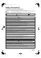
01_EN_3P147083-2F.fm Page 1 Friday, October 28, 2005 9:29 AM Safety Precautions • Read these Safety Precautions carefully to ensure correct installation. • This manual classifies the precautions into WARNING and CAUTION. Be sure to follow all the precautions below: they are all important for ensuring safety. WARNING...............Failure to follow any of WARNING is likely to result in such grave consequences as death or serious injury. CAUTION...............
01_EN_3P147083-2F.
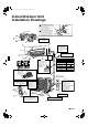
01_EN_3P147083-2F.fm Page 3 Friday, October 28, 2005 9:29 AM Indoor/Outdoor Unit Installation Drawings How to attach the indoor unit. Hook the claws of the bottom frame to the mounting plate. If the claws are difficult to hook, remove the front grille. A Mounting plate Clip How to remove the indoor unit. Push up the marked area (at the lower part of the front grille) to release the claws. If it is difficult to Front grille release, remove the front grille.
01_EN_3P147083-2F.fm Page 4 Friday, October 28, 2005 9:29 AM Outdoor Unit Installation Guidelines • Where a wall or other obstacle is in the path of outdoor unit’s intake or exhaust airflow, follow the installation guidelines below.
01_EN_3P147083-2F.fm Page 5 Friday, October 28, 2005 9:29 AM Indoor Unit 1. Installing the mounting plate. • The mounting plate should be installed on a wall which can support the weight of the indoor unit. 1) Temporarily secure the mounting plate to the wall, make sure that the panel is completely level, and mark the boring points on the wall. 2) Secure the mounting plate to the wall with screws.
01_EN_3P147083-2F.fm Page 6 Friday, October 28, 2005 9:29 AM 3. Installing indoor unit. 3-1. Right-side, right-back, or right-bottom piping. 1) Attach the drain hose to the underside of the refrigerant pipes with adhesive vinyl tape. 2) Wrap the refrigerant pipes and drain hose together with insulation tape.
01_EN_3P147083-2F.fm Page 7 Friday, October 28, 2005 9:29 AM Indoor Unit Note: 1) Wrap the refrigerant pipes and drain hose together with insulation tape as right figure, in case of setting the drain hose through the back of the indoor unit. 2) If it difficult to fix the claws of the bottom frame on the catches of the mounting plate. Secure indoor unit to the mounting plate with scres (M4 × 12L). Drain hose A Mounting plate Refrigerant pipes Bottom frame 3-3. Wall embedded piping.
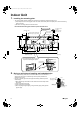
01_EN_3P147083-2F.fm Page 8 Friday, October 28, 2005 9:29 AM Terminal block 1 2 3 4 Electrical component box Wire retainer Shape wires so that the service lid will fit securely. Firmly secure wire retainer so that wires sustain no external stress. Use the specified wire type. Firmly fix the wires with the terminal screws. When wire length exceeds 10m, use 2.0mm wires. Outdoor unit 12 34 LN The earth leakage circuit breaker is required depending on site environment.
01_EN_3P147083-2F.fm Page 9 Friday, October 28, 2005 9:29 AM Outdoor Unit 1. Installing outdoor unit. • For outdoor unit installation, see Choosing a Site Outdoor unit 2. and Indoor/Outdoor Unit Installation Drawings. Flaring the pipe end. 1) Cut the pipe end with a pipe cutter. 2) Remove burrs with the cut surface facing downward so that the chips do not enter the pipe. 3) Put the flare nut on the pipe. 4) Flare the pipe. 5) Check that the flaring is properly made. (Cut exactly at right angles.
01_EN_3P147083-2F.fm Page 10 Friday, October 28, 2005 9:29 AM 4. Purging air and checking gas leakage. • When piping work is completed, it is necessary to purge the air and check for gas leakage. WARNING 1) 2) 3) 4) Do not mix any substance other than the specified refrigerant (R410A) into the refrigeration cycle. When refrigerant gas leaks occur, ventilate the room as soon and as much as possible.
01_EN_3P147083-2F.fm Page 11 Friday, October 28, 2005 9:29 AM Outdoor Unit 5. Pump down operation. In order to protect the environment, be sure to pump down when relocating or disposing of the unit. 1) Remove the valve lid from liquid shut-off valve and gas shut-off valve. 2) Carry out forced cooling operation. 3) After five to ten minutes, close the liquid shut-off valve with a hexagonal wrench. 4) After two to three minutes, close the gas shut-off valve and stop forced cooling operation.
01_EN_3P147083-2F.fm Page 12 Friday, October 28, 2005 9:29 AM To connect the wires, remove the screw and pull up the terminal block cover. After the wiring is complete, return the cover to its original location and secure with the screws. Terminal block cover Screw 1 2 4 3 L N Power supply terminal block Plug in the connector fully. Secure the thermistor cable with a wiring tie so that no external stress is applied to the connector.
01_EN_3P147083-2F.fm Page 13 Friday, October 28, 2005 9:29 AM Outdoor Unit 7. Drain work. Drain-water hole 1) Use drain plug M for drainage. 2) If the drain port is covered by a mounting base or floor surface, place additional foot bases of at least 30mm in height under the outdoor unit’s feet. 3) In cold areas, do not use a drain hose with the outdoor unit. (Otherwise, drain water may freeze, impairing heating performance.) Bottom frame M Drain plug Hose (available commercially, inner dia.
00_CV_3P147083-2F.