
Service manual

2-4
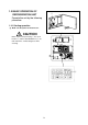
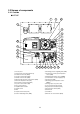
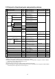
2.2.3 Control box
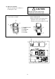
q Controller operation panel (EC3, 4)
w MANUAL DEFROST key
e UNIT ON/OFF key
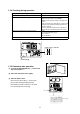
r Phase correction contactor (PCC1,2)
t Magnetic contactor for high speed evaporator fan (EFH)
y Magnetic contactor for low speed evaporator fan (EFL)
u Magnetic contactor condenser fan (CFC)
i Reverse phase protection device (RPP)
o Adopter PCB (EC6)
!0 Terminal block board (TB1)
!1 Controller CPU / IO board (EC1, 2)
!2 Fuse (Fu1-6)
!3 Rechargeable battery (BAT)
!4 Voltage indicator
!5 Personal computer receptacle
!6 Circuit breaker (CB)
!7 PT/CT board
!8 Transformer (TrC), control circuit
!9 Magnetic contactor for compressor (CC)
@0 P.C.B for humidity sensor (HUS, optional)
@1 Modem (RCD, optional)
@2 Noise filter (NF, optional)
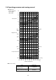
●Operation panel
(Outside of the control box)
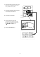
●Controller
●Inside of the control box
2
3
1
3
1
2
b
–12 –10 –8 –6 –4 –2
–2–3–4–5–6 –1
SP–5
OVER
2
INRANGE
HOURS
DAYS
1
UNDER
ALARM
R.H.
SUPPLY
RETURN
˚C / ˚F
%R H
DEFROST INRANGED–HUMID
COMP.
˚C
˚C
SP+
5
DECOS
DAIKIN ELECTRONICCONTAINER OPERATION SYSTEM
20
PAK-61JC
10
9
22
15 21
4
14
17
5
11
13
11
16
8
PAK-61JC
19
PAK-61JC
12
7
18
B4P–VH B4P–VH
FUSE
6
B3PSVH
RA–H341TD
B5P-VH
35J
PAK-