Head Office. Umeda Center Bldg., 4-12, Nakazakinishi 2-chome, Kita-ku, Osaka, 530-8323 Japan. Tel: 06-6373-4338 Fax: 03-6373-7297 Marine type Container Refrigeration Unit Tokyo Office. Tokyo Opera City Tower 12F. 3-20-2 Nishi-Shinjuku, Shinjuku-ku, Tokyo 163-1412, Japan. Tel: 03-5353-7860 Fax: 03-5353-7913 Service Manual $5,00 (2002.11.
Please read the contents of this manual prior to operation of the unit. This booklet will provide you with the minimum necessary information required to operate the Daikin refrigerated unit LXE10E-A. It covers all of the unit's functions from basics such as the names for each mode of operation, how to turn on the power supply, or change a setting temperature, to describing functions of product and maintenance service.
CONTENTS Safety Precautions • Danger .................................................................3 • Warning................................................................4 • Caution.................................................................5 1. Introduction .......................................................1-1 1.1 Operation range ............................................1-1 1.2 Basic Names of components ........................1-1 1.3 Basic operation of refrigeration unit ..............
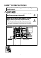
SAFETY PRECAUTIONS Always observe the following points before operating or inspecting a unit. DANGER Always turn off the main power supply to the facility before disconnecting the power plug. Always turn off the main power supply to the facility before inspecting the interior of the control box. ※This is important because high voltage remains at the circuit breaker and the optionally provided modem even though the circuit breaker in the control box is turned off.
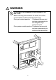
WARNING Do not touch the condenser fan while power to the unit is ON. Before removing the condenser fan cover, turn off the circuit breaker and disconnect the power plug. During air-cooled operation : Condenser fan may start and stop automatically for the refrigerant high pressure control. During water-cooled operation: Condenser fan may start and stop automatically for cooling of the control box.
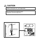
CAUTION Before starting the unit, run the generator. Securely close the control box cover. Otherwise, it will allow water entry.
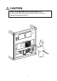
CAUTION Wash the refrigeration unit with fresh water at PTI. Carefully flush the air-cooled condenser with fresh water to remove the salt that sticks to it.
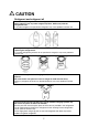
CAUTION Refrigerant and refrigerant oil Be sure to only charge the unit with refrigerant HFC 134a. Never attempt to use any other refrigerant (CFC12, HCF22, etc) with the refrigeration unit. If any other refrigerant not specified is charged, it may cause problems with the unit. Use only Daikin specified oil (IDEMITSU, Daphne Hermetic Oil FVC46D) when replacing the refrigerant oil. If any other refrigerating machine oil not specified is charged, it may cause problems with the unit.
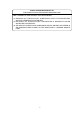
CLASS 1 SPECIFIED PRODUCT BY THE HYDROFLUORIC REFRIGERANT RECOVERY LAW HFC IS USED FOR THIS PRODUCT AS A REFRIGERANT. (1) EMISSION OF HYDROFLUORIC SUBSTANCES INTO THE ATMOSPHERE WITHOUT PERMISSION IS PROHIBITED. (2) RECOVERY OF HYDROFLUORIC SUBSTANCES IS MANDATORY WHEN SCRAPPING THIS PRODUCT. (3) THE KIND OF HYDROFLUORIC SUBSTANCE AND ITS AMOUNT ARE STATED IN THE MANUFACTURER'S LABEL OR THE ADDITIONALLY CHARGED AMOUNT LABEL.
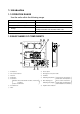
1. Introduction 1.1 OPERATION RANGE Use the units within the following range. Item Operation range Ambient temperature range -30˚C to +50˚C (-22˚F to + 122˚F) Inside temperature range -30˚C to +30˚C (-22˚F to + 86˚F) Voltage 50Hz: 380V/400V/415V, 60Hz: 440V/460V Voltage fluctuation rate should be within ±10% Vibration and shock 2G 1.
1.3 BASIC OPERATION OF REFRIGERATION UNIT w Operate the unit by the following procedure. 1.3.1 Starting operation (1) Make sure that power to the unit is on. CAUTION Make sure that the power plug q, the circuit breaker w, and the UNIT ON/OFF key e are OFF. Otherwise, it will be dangerous while checking.
(2) Adjust the ventilation. Adjust the opening of the ventilation !0 according to the cargo. CAUTION Keep the ventilation closed during transportation of the frozen cargo. When ventilation is not required (frozen mode), set the handle to "CLOSE". When ventilation is required (chilled mode), slide the handle upward. ※Set the arrow mark of the ventilation at the graduation on the scale to adjust the ventilation as desired according to the cargo.
(3) Connect the power plug to the power supply. Insert the plug !6 suited to the power source voltage, and fasten the plug firmly. (4) Turn on the main power switch of the power source facility (outside the unit) !6 (5) Turn on the circuit breaker !7. Power plug (6) Close the control box cover fully. If it is poorly closed, it will allow water entry. Check the contact around the packing, and firmly close the cover. (Refer to the " CAUTION " on page 5.) !7 (7) Press the UNIT ON/OFF key !8.
1.3.2 Checking during operation Checking items(precautions) Method of check 1. Check the compressor, fan, pipes, etc. for abnormal noise and vibration. Visual and auditory Visual 2. Check the refrigerant for shortage. Bubbles in moisture indicator on PULLDOWN or FROZEN operation may mean shortage of refrigerant in the system. Charge specified amount of refrigerant to the system, if inside temperature cannot maintain the setting temperature due to shortage of refrigerant.
2. General description 2.1 Main specifications Model LXE10E Item Condenser cooling system Controller DECOS3C Power supply AC 3-phase 380V/400V/415V 50Hz, 440V/460V 60Hz Compressor Hermetic scroll type (Motor output: 5.
2.2 Names of components 2.2.
2.2.
2.2.3 Control box ●Inside of the control box 4 5 6 8 20 9 10 7 19 22 PAK35J PAK-61JC PAK-61JC PAK-61JC 18 B4P–VH B4P–VH 17 16 FUSE B5P-VH B3PSVH RA–H341TD 15 21 12 11 ●Operation panel (Outside of the control box) COMP. ●Controller OVER SP+ ˚C 5 INRANGE UNDER S P – 5 ˚C 1 DEFROST INRANGED–HUMID SUPPLY RETURN ALARM R.H.
2.3 Set point of functional parts and protection devices Pressure switch Device name Actuation High-pressure switch HPS Water pressure switch OFF 98kPa (1.0kg/cm2) Water pressure switch WPS (optional) ON ON 39kPa (0.4kg/cm ) +30.0°C to –2.9°C Set point temperature EC 2 (+86.0°F to +26.8°F) –3.0°C to –10.0°C Partial frozen mode (+26.6°F to +14.0°F) Frozen mode –10.1°C to –30.0°C (+13.8°F to –22.
2.4 Operating pressure and running current ●Chilled mode Inside : 0°C (32°F) Power supply : 400V / 60Hz 16 15 14 13 12 Total current 11 10 9 8 7 2 (kPa) (kg/cm) 2000 20 High pressure 1500 15 1000 10 500 5 0 0 (kg/cm2) (kPa) 200 2.0 Low pressure 100 1.
●Frozen mode Inside: –18˚C (–0.4˚F) 16 Power supply: 400V, 60Hz 15 14 13 12 Total current 11 10 9 8 7 (kPa) (kg/cm2) 2000 20 High pressure 1500 15 1000 10 500 5 0 0 (kg/cm2) (kPa) 200 2.0 Low pressure 100 1.0 0 0 –100 5 (41 10 50 –76B Hg 15 20 25 30 35 40 45 50 (˚C) 59 68 77 86 95 104 113 122) ( F ) Ambient temperature ˚C (˚F) ●Fan motor current Item Condenser fan motor running current Evaporator fan motor running current (2 motors) 2-7 Amperage 1.4 (400VAC) 0.
2.5 OPERATION MODES AND CONTROL There are two main types of operation modes: the cargo cooling control mode and the unit inspection mode. The cargo cooling control mode is explained in this section. ※For the unit inspection mode, refer to section 3.9. The relationship between the operation mode and setting temperature is as follows. Operation mode Setting temperature –10.1˚C to –30.0˚C (+13.8˚F to –22.0˚F) Control sensor Return air temperature sensor Partial frozen mode –3.0˚C to –10.0˚C (+26.
2.5.1 Frozen mode Control state transition and common control Thermostat ON (Pull-down range) ●Compressor Running ●Evaporator fan Low speed (L) Continuous compressor running for 2 minutes or more and RS ≤ SP RS > SP + 1.
(1) Set point temperature and control sensor When the set point temperature (referred to as SP hereafter) is –10.1˚C(+13.8˚F) or lower, the compressor is operated ON and OFF, in response to return air temperature. (2) Control qWhen the control temperature reaches SP (point A), the compressor and condenser fan are turned off after the liquid solenoid valve has been de-energized and the pump down operation has been completed. wWhen the control temperature exceeds SP+1.
2.5.2 Chilled and partial frozen mode Control state transition and common control START TS≧SP+1.5˚C TS
(1) Set point temperature and control sensor ™Chilled operation When the set point temperature is –2.9˚C (+26.8˚F) or higher, the suction modulating valve (SMV) is controlled sensing the supply air temperature in order to adjust the cooling capacity. ™Partial frozen operation When the set point temperature is –3.0 to –10.0˚C (+26.6 to +14.0˚F), the suction modulating valve is controlled sensing the return air temperature in order to adjust the refrigerating capacity.
2.5.3 Defrosting mode Start defrosting Yes ●Defrost lamp (red) ON ●Pump down Defrosting range ●Compressor ●Evaporator fan ●Condenser fan ●Defrosting solenoid valve ●Hot gas solenoid valve ON OFF ON/OFF ON ON Is terminating condition OK? No Yes Defrosting lamp (red) OFF Evaporator fan On after delay of 60 seconds Return to frozen, chilled or partial frozen operation Solenoid valve Magnetic contactor Operation of magnetic contactor and solenoid valve Component name Compressor Evaporator fan.
Defrosting operation (1) Defrosting system A hot-gas defrost system is adopted in the units; i.e. the high temperature and high pressure refrigerant (hot gas) from the compressor is sent to the evaporator and drain pan for defrosting. Since the evaporator is heated directly by the hot gas (refrigerant), defrosting can be performed effectively. (2) Defrosting initiation Defrosting is initiated by the timer or the manual defrost key.
(4) Defrosting termination Defrosting will be terminated when any one of the following three conditions is satisfied. qThe below figure is satisfied during defrost. Status before defrost INRANGE OUTRANGE Termination EOS≧30.0˚C EOS≧30.0˚C+RS/DRS≧15˚C w90 minutes have elapsed. eAny one of protective devices is activated.
2.5.4 Common control The following are controlled in different operation modes. (For the details, refer to the following pages.) Control name Control content The compressor is operated on and off to adjust the inside temperature. At the start of the operation with low ambient Starting control temperature,an oil temperature raising control is executed. When a protection device activates at the operation start, a high pressure/current control is executed.
Common control A : Compressor ON/OFF control When the control temperature reaches the set temperature or lower, the compressor is stopped. When the control temperature rises and becomes higher than the [set point temperature +1.0˚C], the compressor runs again. When the compressor starts running it is forcibly run for 2 minutes. (2 minutes compressor forced operation) in order to prevent the compressor from deterioration due to shortage of lubricant.
Dehumidification : OFF Dehumidification : ON High pressure ≦ 800kPa High pressure ≦ 700~1800kPa ON ON OFF OFF High pressure > 1000kPa High pressure > 900~2100kPa F : Injection control In order to decrease the discharge gas temperature, inject liquid refrigerant into the suction pipe. • During normal compressor operation The injection solenoid valve will be turned on or off to control the discharge gas temperature lower than set point.
J : Charge and release control Charge control or release control is executed to maintain the heating capacity optimum in defrosting and heating operation. • Charge control LPT > 70 kPa qThe suction pressure (LPT) is detected and the injection ON solenoid valve (ISV) is turned on, then, liquid refrigerant is charged into the suction pipe.
N : Bulb mode ※If reheat coil and humidity sensor (Optional) is equipped: For bulb transportation, bulb mode is provided as below. To execute bulb mode, controller setting is required. (Refer to Page 3-12) In bulb mode operation, character "b" is shown on 1st segment on LED display. The following setting can be made. 1) Dehumidification: On/Off If this is On, dehumidification range can be set between 60%RH–95%RH, starting at 95%RH.
3. ELECTRONIC CONTROLLER 3.1 Function table ●DECOS 3c (Daikin Electronic Controller Operation System) (Note) [PC]: Functions using personal computer No.
No.
3.2 BASIC OPERATION OF ELECTRONIC CONTROLLER 3.2.1 Control panel Name and function of each components t y u q i w e COMP. SUPPLY RETURN ALARM R.H. r OVER SP+5 ˚C o DEFROST INRANGE DEHUMID ˚C / ˚F %R H 1 INRANGE 2 3 UNDER S P – 5 ˚C !0 1 HOURS 2 DAYS –12 –6 –10 –5 –8 –4 –6 –3 –4 –2 DAIKIN ELECTRONICCONTAINER OPERATION SYSTEM –2 –1 DECOS b Operation key q SUPPLY LED (Lights when "supply air temperature" is indicated.) w RETURN LED (Lights when "return air temperature" is indicated.
Function of operation key UNIT ON/OFF ●UNIT ON/OFF key UP ●UP key To select the item to be set in the selected mode. To start or to stop the unit operation. The controller has a memory DOWN function. If the power supply is cut off ●DOWN key To select the item to be set in the selected mode. suddenly while the unit is on, and the power supply is then ENTER/ESC turned on again, the unit ●ENTER/ESCAPE key To determine the setting values or displayed contents in the selected mode.
DISPLAY ˚C ˚F q Indicate the temperature data required to be converted into "˚F" on the LEDDISPLAY or the LCD. Press the ˚C ˚F key, then the temperature data displayed in "˚C" is converted into "˚F" for one minute. ※ If any other key is pressed during the "˚F" indication, the display switches to "˚C". 「℃」display 「°F」display LED LCD MANUAL DEFROST MANUAL DEFROST qPress the MANUAL DEFROST key.
3.3 Operation procedure 3.3.1 Operation procedure flow chart S Power off ※3 Battery mode No key operation for 30 sec. Circuit Breaker ON Unit off I/O ON I/O OFF All Lighting (for 3 sec.) for 3 sec. PTI Refer to page 3-54 Preparation (for 18 sec.) S Current indication ※1 ※2 Operation Setting (Set Point ˚C, Humidity %, Defrost Internal) or no key operation for 5 min. ※8 Alarm Record Scroll ※7 Temperature Record Scroll ※6 Sensor Indication ※9 PTI Record Scroll or no key operation for 5 min.
Check on settings and operation conditions ※1. Current indication mode (indication of operation conditions) Indicates the unit operation conditions. ※2. Operation setting mode Settings for cargo transportation ●Supply air temperature (SS) ●Return air temperature (RS) ●Defrost interval ●Alarm ●Setting point humidity and humidity (OPTION) ●Temperature settings ●Defrost interval settings ●Humidity settings (optional) P 3-9 P 3-10 ※3.
Indication of detailed data alarm and PTI ※6. Sensor indication mode Each sensor value can be indicated.
3.3.2 Mode operation procedure 1. CURRENT (Operation state) INDICATION MODE Supply air temperature (SS), return air temperature (RS), defrosting interval, currently existing alarm, set point humidity, and humidity are indicated. POWER OFF Circuit breaker: ON UNIT ON/OFF Key: ON CURRENT (Operation state) INDICATION MODE Select an item using the or LED display and LCD display.
2. OPERATION SETTING MODE Control temperature, defrosting interval, and control humidity (optional) can be set. CURRENT (Operation state) INDICATION MODE To change to the OPERATION SETTING MODE, press the S key while the unit is in the CURRENT INDICATION MODE. key or nonoperation for 5 minutes S OPERATION SETTING MODE In the OPERATION SETTING MODE, Control temperature, Control humidity (optional) and Defrosting interval can be set. Select an item using the S key.
3. BATTERY MODE When commercial power is not available, the following functions are available by using the built-in wake up battery. • Indication of inside supply air temperature (SS) and return air temperature (RS) • Setting for control temperature, control humidity and defrost interval To change to the BATTERY MODE, press the S key while the unit is in the POWER OFF STATUS.
4. MODE OPERATION MODE M Press the key in current indication mode to go to MODE operation. All indication Lights on (for 3 sec.) Starting Preparation (for 18 sec.) ※1 Current indication (Operation state) MODE M MODE OPERATION In mode operation, the following settings/operations are available. 1. Generator setting Total power consumption can be reduced to desired Max setting for the specific generators set or power facilities. The selections are "off (No limit)", "15" "14" "13" "12" "11" KVA. 2.
5. Dehumidification mode setting Dehumidification mode can be executed in this mode (M. Dehumidification mode control in 2.5.4). When "Dehumidification" is set to "on", it is possible to change the following set from default. qInside humidity : 95% (Default) ~60% RH wEvaporator fan speed : Alterating (H-L) (default) / High / Low IMPORTANT When Full PTI is executed, settings of "Bulb" and "Dehumidification" are reset to default automatically.
Setting item LED panel LCD panel Setting method –– –– –– Current indication mode MODE M OFF, 11, 12, 13, 14, 15 unit: kVA G-SET G-set operation Note 1) Select the energy saving set point by using or key, and press the key to determine the setting. MODE M Automatic pump down operation ON, OFF P down Select "ON" by using key and MODE MODE M M LED Display Light off setting Note 2) key, and press the key to determine the setting.
Setting item LED panel LCD panel ON, OFF Hu Setting method Select desired setting by Dehumidification or press (OFF) MODE (ON) MODE M M 95% RH~60% RH Shu key, then key. Select desired setting Humidity set by or press key, then key. MODE M Evaporator fan speed H-L, H, L FAN Select desired setting by or press key, then key. MODE M Defrost termination temperature +4.0~+18.0˚C (max RS temp) DEF END Select desired setting by or press key, then key.
Setting item LED panel LCD panel 95% RH~60% RH Shu Setting method Select desired setting by Humidity set key or then press determine. key, key to MODE M Evaporator fan speed H-L, H, L FAN Select desired setting by MODE key or then press determine.
5. LED display LIGHT-OFF MODE The controller LED display is turned off with this mode. ※ Activation of the panel (LED) lighting off mode. To activate the panel (LED) lighting off mode, set the LED lighting off function "dISP" in "11. Basic setting mode" to ON. Refer to page 3-30. All indication Lights on (for 3 sec.) Starting Preparation (for 18 sec.
6. SENSOR INDICATION MODE Each sensor value, the modulating valve (MV) opening, and the electronic expansion valve (EV) opening can be checked.
6. SENSOR INDICATION MODE (continued) CURRENT SENSOR-2 (CT2) AMBIENT TEMPERATURE SENSOR (AMBS) LED: The control temperature is displayed. LCD: The compressor running current is displayed. The display reads: " 2 CT A". (In Ampere.) LED: The control temperature is displayed. LCD: The ambient temperature is displayed. The display reads: "Ab C". (In ˚C or ˚F.) EVAPORATOR INLET TEMPERATURE SENSOR (EIS) LED: The control temperature is displayed. LCD: The evaporator inlet temperature is displayed.
6. SENSOR INDICATION MODE (continued) PULP TEMPERATURE SENSOR 1 (USDA 1) (optional) LED: The control temperature is displayed. LCD: The pulp temperature is displayed. The display reads: " 1 US C". (In ˚C or ˚F.) PULP TEMPERATURE SENSOR 2 (USDA 2) (optional) LED: The control temperature is displayed. LCD: The pulp temperature is displayed. The display reads: " 2 US C". (In ˚C or ˚F.) PULP TEMPERATURE SENSOR 3 (USDA 3) (optional) LED: The control temperature is displayed.
7. TEMPERATURE RECORD SCROLL MODE The control sensor value record is shown in sequence (scroll) starting with the latest data. The latest control temperatures for a maximum of 7 days are displayed. All indication Lights on (for 3 sec.) Starting Preparation (for 18 sec.
Temperature record scroll function The control sensor value record for the last 7 days is displayed in sequence (scroll) beginning with the latest one and ending with oldest one, so that easy inspection of the previous operation data is enabled on board. The LED indicates the control temperature, and the LCD displays the data or time and the non-control temperature in turn.
● Example of TEMPERATURE RECORD SCROLL INDICATION MODE ※ It is assumed that the control temperature is the supply air temperature (SS) and the logging interval is 1 hour, and the current date and time are June 27, 2002, 14:00. q COMP. DEFROST IN RANGE DE-HUMID. SUPPLY RETURN ALARM R.H. ------------- 27 0. 1 1 3. 0 0 --------- An example. p.m. 1:00 June 27, 2002 (To be displayed on LCD) SS= – 0.1 ˚C (indicated on LED) SUPPLY LED lights on. ALARM LED lights on (when alarms exist).
8. ALARM RECORD SCROLL MODE The alarm record is shown in sequence (scroll) starting with the latest data. The latest alarms for a maximum of 7 days are displayed. All indication Lights on (for 3 sec.) Starting Preparation (for 18 sec.) ※1 Current indication (Operation state) ※ 7 Temperature Record Scroll ※ 6 Sensor Indication ※ 8 Alarm Record Scroll The LED indicates the alarm codes and the LCD displays date and time.
Alarm record scroll function The alarms detected over the last 7 days are displayed on the controller which scrolls through them at the rate of one sec/alarm. < Operation procedure > The LED indicates alarm codes, and the LCD displays date and time. To pauze the scrolling action, press the press the or or key. To advance to the next alarm code detected, key again. If arrow key is not pressed for 10 seconds, then the continuous scrolling action is resumed.
9. PTI RECORD SCROLL MODE The record is shown in sequence (scroll) starting with the latest data. All indication Lights on (for 3 sec.) Starting Preparation (for 18 sec.) ※1 Current indication (Operation state) ※ 7 Temperature Record Scroll ※ 6 Sensor Indication ※ 8 Alarm Record Scroll ※ 9 PTI record scroll PTI record scroll function COMP.
3.3.3 Setting flow chart This configuration setting flow shall be utilized, when CASE 1) USDA transportation setting is required (※10 Optional Function Setting) CASE 2) Logging intervals shall be changed from default setting (60 min). (※11 Basic Function Setting) CASE 3) Setting of any H / d codes shall be changed from default. (※12 Optional Condition Setting) CASE 4) Container ID shall to be subjected to change from another container for emergency use.
Controller initial setting ※10. Optional function mode ●USDA sensor setting ●Dehumidification control on/off setting P 3-29 ※11. Basic function setting mode ●Controller type ●Compressor unload ●Reheat coil ●Logging interval ●Data recorder sensor on/off ●Power supply ●Compressor horse power ●Indication (LED section) light off function P 3-30 P 3-31 on/off ※12.
10. OPTIONAL FUNCTION SETTING MODE Power OFF Circuit Breaker ON Circuit Breaker OFF after setting change Unit OFF ( I/O OFF when no setting changed) I/O ON All indication lights on (for 3 sec.) I/O OFF for 3 sec. for 3 sec. F. PTI S. PTI M. CHECK Starting preparation (for 18 sec.) ※ 10 Optional Function Setting ※1 Current indication (Operation state) Whenever the S key is pressed, the display changes.
11. BASIC FUNCTION SETTING MODE Power OFF Circuit Breaker ON Circuit Breaker OFF after setting change Unit OFF ( I/O OFF when no setting changed) I/O ON All indication lights on (for 3 sec.) I/O OFF for 3 sec. F. PTI S. PTI M. CHECK Starting preparation (for 18 sec.) for 3 sec. for 3 sec. ※ 10 Optional Function Setting ※ 11 Basic Function Setting ※1 Current indication (Operation state) Whenever the S key is pressed, the display changes.
S INPUT POWER SETTING S To set the power input: Select "Sing" or "dUAL" on the LED when the LCD displays "OC-SET" . Whenever the or key is pressed, the indication of "Sing" or "dUAL" is changed. Press the key to determine the setting. For the unit, select "Sing", and press key to determine the setting. S HORSEPOWER SETTING S LED DISPLAY LIGHT-OFF SETTING To set the horse power setting: Select "5" or "10" on the LED when the LCD displays "HP" (Horse power). Whenever the or changed.
12. OPTIONAL CONDITION SETTING MODE Power OFF Circuit Breaker ON Circuit Breaker OFF after setting change Unit OFF ( I/O OFF when no setting changed) I/O ON All indication lights on (for 3 sec.) I/O OFF for 3 sec. for 3 sec. F. PTI S. PTI M. CHECK Starting preparation (for 18 sec.) for 3 sec. ※ 10 Optional Function Setting ※ 11 Basic Function Setting for 3 sec.
12. OPTIONAL CONDITION SETTING MODE (continued) H002 S H003 S H004 S S H005 S H006 S d1 – – S H002 code is displayed when the integrated time of Out-of "In-Range" reaches 2 hours. Select "1"hour, "2"hours, "3"hours, "4"hours, "5"hours or "10"hours on the LED when the LCD displays "H002". Whenever the or key is pressed, the indication of the selection from "1"hour to "10"hours changes. Press the key to determine the setting. Refer to page 3-66.
12. OPTIONAL CONDITION SETTING MODE (continued) "d2 – –" message displays the total time in hours, that the temperature was above set point +2°C. The code will be displayed after the selected time which can be set to: "1"hour, "2"hours, "3"hours, "4"hours, "5"hours, or "10"hours. When the total time above set point +2°C reaches "1"hour, the code "d101" will be displayed. Whenever the or key is pressed, the selection from "1"hour to "10"hours changes. Press the key to determine the setting.
Whenever the S key is pressed, the indication changes. Turn OFF the power breaker to confirm the setting. CONTAINER I.D. (No.) INPUT S S To input the container I.D. (No.): Press the key when the LCD displays "SET I.d", then display "i.d.C" (name of shipping company input with alphabetical character) or "i.d.-n" (number input with numerical character) on the LED by using or key. To input the shipping company name (alphabet): Press the key when the LED displays "i.d.
3.4 Alarm display and back-up function 3.4.
PF : Partial Frozen 3.4.2 Back-up operation at sensor malfunction Sensor malfunction SS RS Supply air temperature sensor Return air temperature sensor Mode Back-up content Chilled The same control is executed by using DSS (optional). In case of DSS malfunction, [RS–2.0˚C] is used for control. When DSS and RS are faulty, the unit should be stopped.
●Back-up for temperature sensors (EIS, EOS, SGS) at frozen mode (superheat control) Evaporator inlet sensor Evaporator outlet sensor Compressor suction gas sensor Back-up operation No.
3.5 Battery 3.5.1 Specifications DECOS 3c controller can use two types of batteries; Alkaline or Rechargeable (Optional). It is not possible to exchange the type of battery afterwards. The battery is positioned on CPU & I/O box in controller box. Alkaline: 9V block battery. (This can be purchased locally.) Rechargeable: DAIKIN original rechargeable battery 3.5.2 Function This battery is used without main power supply for the following functions.
3.5.
3.6 Information interchange with personal computer The electronic controller DECOS 3c has a internal memory function to record the set point temperature, inside temperature, operation mode, occurrence alarm and the report of automatic PTI during transportation in addition to the normal operation control.
3.6.1 Data logging The data logging function is to store operation data which is generated during navigation. There are seven kinds of logging data. As to Tripdata, its logging interval can select from 15, 30, 60 (default) and 120 minutes. ※When F. PTI is executed, the logging interval become default (Refer to 3.9.2.3) ※Controller has Max. 2 years capacity at 60 min log interval.
3.6.2 SOFTWARE CONFIGURATION SUB MENU TRIP DATA USDA DATA 4-PULP SENSORS DATA PTI DATA ALL DATA AFTER TRIP-START CONTAINER I.D. SET CONTAINER I.D. /HEADER /HEADER -From DISK FIELD JOB MAIN MENU LOGGER DATA DOWNLOAD MAINTENANCE & REPAIR Explanation of functions Remarks Data recorded in the logger is read No information from the controller onto the personal appears on the computer (disk or hard disk). screen at this time. (This operation is called the download).
CONFIG SET OFFICE JOB MAIN MENU MAKE REPORT SUB MENU TRIP REPORT USDA REPORT 4-PULP SENSOR REPORT PTI REPORT ALARM REPORT MONITOR REPORT EVENT REPORT MAKE SET CONTAINER I.D. CONTAINER I.D. /HEADER into DISK /HEADER • CHART MARK • SELECT JOB • CRT MODEL • TRIP REPORT • SET TIME ZONE • G.M.T-LOCAL TIME Explanation of functions Reports are made based on record data read from the logger. Disk data to change LOGGER HEADER of controller is created. Environment using personal computer software is set.
3.7 Inspection procedure for the electronic controller DECOS 3c enables the internal data of the controller CPU (RAM data) to be displayed on the monitor of a personal computer by connecting the two with a communication cable. This makes it possible to preform an easy inspection of the controller and diagnose any defect. (1) Inspection of sensors The inspection is carried out by comparing the sensor readings on the controller display with the display on the personal computer.
3.8 Controller replacement and initial setting 3.8.1 Controller replacement (1) Remove the indication board cover q . (2) Open the clamp e fixing the connector harness w and disconnect the harness. (3) Remove the speed bolts r (2 pcs) from the controller, and open the controller, then disconnect the connector t . (4) Remove the indication board y and the sheet key u . (5) Loosen the screws i (10 pcs) to remove the operation panel o .
(1) Remove speed bolts (2 pcs) on the controller body, then remove the connector. Be sure to keep voltage indicator, the battery and the battery fixing plate for reinstallation.
3-48 OPERATION OPERATION CONDITION SETTING TRIP START SETTING INITIAL SETTING for 4 MODES Circuit Breaker : ON : Manual action ※11 Basic Function Setting Mode (Refer to Page 3-30) PTI selection mode (for Trip Start Setting) 1. Select「Manual Check」with or Key and determine it with Key. 2. Select Trip Start「TS H」with or Key and set it by pressing the Enter Key for 3 seconds.
3.9. PTI (Pre-Trip Inspection) AND PERIODIC INSPECTION The controller (DECOS 3c) has the automatic PTI function, which consists of three process of SHORT PTI (referred to as S.PTI hereafter), FULL PTI (referred to as F.PTI hereafter) and MANUAL CHECK (referred to as M.CHECK hereafter) Mode S.PTI F.PTI M.CHECK Operation description The components are inspected for abnormalities. Even if any abnormal components are found, all processes are executed. S.PTI + unit cooling capacity inspection are executed.
3.9.1 Inspection item The periodic inspection and adjustment of components (if required) is recommended to ensure continued successful operation. The following table shows an example of the inspection plan. No.
Refrigeration system No.
Others Electrical system No.
3.9.2 Automatic PTI (Pre-Trip Inspection) ● The automatic PTI function is provided so as to ensure correct inspection and to shorten inspection time. (1) Appearance inspection of unit q Physical damage w Casing insulation through hole area e Drain hose (dust and clogging) r Power cable and plug damage t Condition of refrigerant piping fasteners.
3.9.2.1 PTI SELECTION MODE The test mode of FULL (F.PTI), SHORT PTI (S.PTI), and MANUAL CHECK (M.CHECK) can be selected. Power OFF Circuit Breaker ON Unit OFF I/O ON All indication Lights on (for 3 sec.) I/O OFF for 3 sec. F. PTI S. PTI M. CHECK Starting Preparation (for 18 sec.) ※1 Current indication (Operation state) Whenever the or FULL PTI SHORT PTI MANUAL CHECK key is pressed, the indication changes. To start FULL PTI, press the LCD.
● Automatic PTI enable conditions Water cooled operation Air cooled operation S. PTI ✕ F. PTI ✕ M. CHECK Ambient temperature condition –10˚C < Ambient temperature ≦ 43˚C When the ambient temperature is above 43˚C or below –10˚C, the result may be abnormal. –10˚C ≦ Ambient temperature ≦ 43˚C When the ambient temperature is above 43˚C or below -10˚C, the following alarm will be indicated. J501: Out of ambient temperature specified conditon. 3.9.2.2 Short PTI (S.
3.9.2.3 Full PTI (F.PTI) F.PTI consists of S.PTI and operation tests. ●Step display and contents (step P00 to P32 are as same as S.PTI) Step P50 P60 ●F.PTI flow chart UNIT ON/OFF key: on Select F.PTI within 18 seconds P70 P80 P90 N Content Check on pull-down to 0˚C Check on controllability of chilled mode operation. Check on defrosting Check on pull-down from 0˚C through -18 ˚C Check on controllability of frozen mode operation S.PTI start P00 to P32 Normal operation F.
IMPORTANT When Full PTI is executed, the following settings are reset to default.
3.9.2.4 Alarm list during PTI (Pre-Trip Inspection) The alarm during automatic PTI are concerned with PTI inspection items in addition to those during normal operation. The alarms at automatic PTI are indicated in J ※※※., being separated from those during normal operation. There are some alarms which are not displayed on the control panel, however, they can be checked referring to the PTI report. Check NO.
3.9.2.5 Manual check (M.CHECK) Since the components are operated individually differing from S.PTI and F.PTI, the steps can be respectively selected and executed. However, any error occuring during execution of M.CHECK will not be included. Turn the UNIT ON/OFF key off to terminate the M.CHECK.
MANUAL CHECK SELECTION MODE The LED displays the values of following items: Compressor operating time, Evaporator fan motor high-speed running current, Evaporator fan motor low-speed running current, Condenser fan motor running current, Battery life, Horse power, Elapsed time after trip start, Evaporator fan motor running time, Condenser fan motor running time, and Controller software version. COMPRESSOR OPERATING TIME To display the compressor operating time: Press the key when the LCD shows "CC ✕10H".
SENSOR CALIBRATION ELAPSED DAYS SINCE LAST. PTI To start calibration for SS, RS, DSS and DRS, press key when LCD displays "CAL". (Refer to sensor calibration in 4.1.14) To display elapsed days since last PTI, press key when LCD displays "DAYS".
3.10. CHARTLESS FUNCTION The controller provides the temperature recorder function. This function, displays the control temperature logging data during operation on the LCD panel in a simple graphic chart so that the data can be confirmed easily. (Chart indication function) The chart, temperature and alarm record scroll indication are based on the control sensor data (SS/RS).
●Displaying temperature change trend: The temperature change trend is shown in the leftmost LCD. However, this display is shown only when all segments are in the same temperature range.
3.10.2 Chartless code display function The chartless code represents the coded inside air temperature. Select "ON" of the chartless code setting to indicate the code on the LED. For the chartless code setting, refer to the "optional conditions setting" on the page 3-32. P code: Indicates the pull-down time. H code: Indicates the abnormal temperature records. d code: Indicates the operation history. 3.10.2.
3.10.2.2 P code (Pull down time indication) The control temperature and pull-down time are indicated alternately during pull-down operation. When the pull-down is completed, the P code will be deleted. P001: Lasts the pull-down for 1 hour. /P002: 2 houes passed since pull-down started. COMP. DEFROST IN RANGE DE-HUMID. COMP. DEFROST IN RANGE DE-HUMID. SUPPLY RETURN ALARM R.H. ------------- SUPPLY P00 1 2P 7 S --------- 1 2. 8. 0 0 RETURN ALARM R.H. LED display alters every 1 sec.
3.10.2.3 H-code H001 =The alarm is displayed when the control temperature does not decrease by 3˚C or more every 4 hours during pull-down operation. Inside Temperature If "t" is smaller than 3˚C, code "H001" appears. ※ This criteria (3˚C) can be adjusted from 1, 2, 5 or 10˚C. t 4Hr SP+1˚C Figure2 SP time H002 =The alarm is displayed when the total time out of "in-range" reaches 2 hours. (Counting is not performed during defrosting).
H005 =The alarm is displayed when the control air temperature is out of "in-range" and defrosting was performed three times while the control air temperature does not return to in-range. SP+1 4Hr SP 4Hr 30min = Figure5 Out range timer H006 =Alarm is displayed when the temperature difference between the control sensor and record sensor is 2˚C for 1 hour, or more.
3.10.2.4 d-code: The d-code shows the current operation state of the unit. Example d101: • This code "d101" will be displayed when the total time above set point +1˚C reaches 1 hour. The code "d102" will then be displayed when the total time above set point +1˚C reaches 2 hours. Example d-21: • This code "d-21" will be displayed when the total time below set point –2˚C reaches 1 hour. The code "d-22" will then be displayed when the total time below set point –2˚C reaches 2 hours.
3.11 Communication modem DECOS 3 c controller has function to transmit operation data through power line, if slave modem (Optional) is provided in control box. (Refer to Control box in 2.2.3) The slave modem shall be complied with ISO10368.
4. Service and maintenance (2) Installation of compressor q Fix the compressor base with bolts Tightening torque: 42.7N m(435 kgf cm) w Apply new gaskets to the suction and discharge flange and fix them with bolts Tightening torque for the suction flange: 25.2N m(257 kgf cm) Tightening torque for the discharge flange: 25.2N m(257 kgf cm) e Tighten the flare nut for intermittent injection and gauge piping. Tightening torque : φ6.4 : 15.7 N m (160 kgf cm) φ9.5 : 36.
™Precautions when removing oil: If the return air temperature inside the container is higher than the ambient temperature, the quantity of oil becomes excessive. In this case, leave the "removing oil label". Conduct the oil removing operation in the PTI mode again after devanning. If removal of the oil is complete at temperature other than that the aforementioned, remove the "removing oil label".
4.1.2 Air-cooled condenser and evaporator 4.1.3 Fusible plug This finned coil is compact and has uniform heat exchanging performance and high heat exchanging efficiency due to the adoption of corrugated fins. ● Washing of air-cooled condenser Carefully flush the air-cooled condenser with fresh water after trip, although this type of condenser employs thick fins and electrodeposition coating for high corrosion resistance.
4.1.4 Drier 4.1.5 Liquid / Moisture indicator The drier automatically absorbs moisture in the refrigerant while it is circulated. It also commonly works as a filter to remove dust in the refrigerant. Replace the drier if it does not absorb moisture or if it is blocked. When installing the new drier, follow the directions given on the label and do not make any mistake about the flow direction of the drier.
(2) Replacing the body q Loosen the lock nut, then remove the coil. w Remove the hexagonal head bolts, and cut the pipe on the body, then remove remaining pipes from brazing parts. e Connect a new body to the pipes. Be sure to conduct brazing work while cooling the body below 120˚C (248˚F) by using wet cloths. r Fix the body to the mounting base. t Remove the cap, and mount the coil with the tightening torque of 6.9 to 16.7 N m (70 to 170kgf cm).
4.1.7 Suction modulation valve q Upper rubber cover The flow rate of suction gas is controlled between 3 to 100% by a stepping motor in order to conduct capacity control operation. e Binding band w Lower rubber cover ass'y 1. Replacing the coil q Lead wire connector ● Coil removing procedure (1) Disconnect the SMV lead wire connector q from the inside of control box. (2) Cut the binding band e at the upper rubber cover q and lower rubber cover w, then remove the rubber cover q.
2. Replacement of body 4.1.8 Solenoid valve (1) Remove the coil. Refer to the section 1. "Replacing the coil" for removing procedure. (2) Remove the heat insulator q for the SMV after cut the binding band w. (3) Heat up the brazed joint on the piping of SMV body to disconnect the pipe at brazed section. (4) Assemble piping of the SMV body, and conduct brazing while keeping the temperature of lower body of SMV below 120˚C (248˚F) by covering the body with wet cloth.
(1) Replacing the coil q Remove the lead wire connector from the inside of the control box, and cut and recover the binding band which fastens the lead wire. w Remove the hexagonal head bolt on the top of the coil to pull the coil out. e Replace the coil with a new one and restore the hexagonal head bolt, the binding band and connector on the original position. When reassembling the coil, the tightening torque should be 2.9 N m (30 kg cm).
4.1.10 Check valve 4.1.11 High-pressure switch (HPS) ● Model LCV(B)5 (1) Replacement procedure q Remove the pipe clamp which fixes the check valve, then heat up the valve to disconnect the brazed joint. w Install the new check valve taking care to install it in the correct direction, which is the same direction as the arrow shown in the label.
y Apply the heat shrinkage tube in the following position, then shrink it with hot air of a dryer. 4.1.12 Low pressure transducer (LPT) ● Model SPCL02 ● Colour indication: Low pressure transducer: Blue Low pressure transducer: cable: White The LPT is located in the refrigerant circuit. The operating low pressure value is displayed on the controller indication panel. (1) Replacing the transducer q Disconnect the lead wire from the control box.
(Example) 4.1.14 Temperature sensor (1) Sensor calibration ● Supply and Return air sensor (SS/RS/DSS/DRS) q Prepare the ice bath w Cut the binding of each sensor and put them into the ice bath e Turn on the unit and display "Sensor calibration (CAL)" in "Manual Check" mode in 3.9.2.5 r Press the key to calibrate 4 sensors *Be sure to check the ice bath temperature is 0 degC.
(2) Replacement q Switch off the unit and disconnect power cable w Disconnect the cable of the defective sensor on the terminal board. Replace the sensor by a new sensor and connect the cable on the terminal board again. (TB1), referring to wiring diagram in 7.12 CAUTION 1. Be sure the colour marker to identify the defective sensor for SS an DSS, RS and DRS. 2. Be sure to execute calibration after replacement for correction of offset figure. 4.1.
● How to use bearing drawing tool on the market. 4.2 Fan and fan motor Motor Fan (1) Specification Bearing drawing tool Evaporator Condenser Model Propeller fan Size 440mm 300mm Model 3-phase squirrel-cage induction motor Output (60Hz) 700/90W 670W (Number of poles) (2P/4P) (4P) Shielded ball Shielded ball Bearing bearing with bearing with rubber seal rubber seal 6203WNC 620400NC-X Boss When the shaft of the bearing drawing tool is short, apply a bolt at the end of the shaft.
4.3 PT and CT board (EC9756) r PTI (R-S voltage) Two function of the measuring device and protector are integrated on this printed-circuit board. This board works as an interface between the main circuit (high voltage) and the controller.
(2-3) Removal of mounting plate Check the following table to see if the mounting plate should be removed. If the mounting plate must be removed, remove the four screws and dismount the mounting plate. Over current setting and removal of mounting plate Spare parts LXE5C Type ––––– Dual 5HP Dual 10HP Single 10HP Over current setting value ––––– 8.
4.4 Maintenance service CAUTION 4.4.1 Collection of refrigerant qWhen release the refrigerant from the refrigerant system, be sure to use a refrigerant recovery unit to protect the ozone layer around the earth from depletion. wObserve strictly all the environmental laws relating with to the country where the repair service is conducted. 1.
●Caution on the service work qBe sure not to bend the refrigerant pipe when pushing the quick joint during connection work. wIf the installation fails due to movement of the sleeve, try it again after returning the Low-pressure side hose sleeve to the original position. eThe remaining pressure in the charge hose may cause installation failure. In this case, Quick joint try it again after relieving the pressure in (Low pressure) the hose.
4.4.3 Automatic pump down An automatic pump down system is applied to the unit to prevent the unit from extra decrease of low pressure due to pump down operation or burning of scroll compressor due to a close stop valve. (1) Controller operation Press the M key twice to select the pump down mode, then, the LCD displays "P down". Select "ON" by using key or key, and press the key to start the automatic pump down operation.
(2) Automatic pump down operation Once the automatic pump down is started, all of the service works from refrigerant collection into the receiver, to the equalizing in suction piping system, can be executed automatically. When "Good" is displayed, service works such as replacing the dryer, etc. can be conducted without any other operation. q [Preperation] Turn on Automatic pump down.
4.4.4 Refrigerant Recovery and Charge (1) Schematic diagram Evaporator BSV service port EV DPR Condenser Check valve w q ESV HSV DSV Drier LSV Receiver SMV Compressor service port r ISV t Service port w q Service work High pressure Pressure Check Low pressure t [1] Refrigerant Recovery r&t [2] Vacuum & Dehydration r&t Refrigerant recovery and charge (R134a: 4.
(2) Recovery non-condensable gas If air or other non-condensable gas exists in the refrigerant circuit, it is accumulated in the condenser, which raises pressure in the condenser abnormally high and reduces the heat transfer ratio of the condenser surface resulting in a decrease of the refrigerating capacity. It is, therefore, very important to remove non-condensable gas.
(5) Vacuum-dehydrating, and refrigerant/refrigerant oil charging If all the refrigerant has leaked out and air is intermixed in the refrigeration circuit, remove the cause of trouble and carry out vacuumdehydrating. Then charge the specified amount of refrigerant. [Required tools] 1. Refrigerant cylinder (content of 20kg) equipped with joint for HFC134a 2. Gauge manifold with quick joints 3. Weighing scale (up to 50kg) 4. Vacuum pump (a) Vacuum dehydrating (Refer page 4.4.
(b) Cylinder weight recording Place a refrigerant cylinder on the weighing scale, and record the weight of the cylinder. CAUTION Carry out the operation check after the replacing and charging of refrigerant, then replace the drier. (c) Charging of liquid refrigerant Connect the cylinder with liquid receiver inlet port t and tilt the cylinder the cock side down. Open the cock while the unit stops and charge the liquid refrigerant. Close the cock when the charged amount reaches to specified value.
4.4.5 Evacuation and dehydrating After repairing the refrigerant system, vacuumdehydrate the system before charging the refrigerant. Vacuum-dehydrating is the process to make the circuit dry by purging the moisture (liquid) in the circuit to outside in state of vapor (gas) using the vacuum pump. As the pressure lowers below normal atmosphere (760mmHg), the boiling point of water rapidly drops. If the boiling point drops beyond the atmospheric temperature, water will be vaporized.
w Vacuum holding test Hold the system at a pressure of –755mmHg or lower for 1 hour or longer, and confirm that the vacuum reading does not rise on the vacuum gauge. If it rises, moisture or leakage may exist in the system. However, take care not to leak air from the gauge manifold. If air enters, it is recommended to use the cupper tube directly instead of gauge manifold. e Charging of refrigerant After the vacuum-holding test, make the circuit vacuous again for approx. 10 minutes.
5. Optional Devices 5.1 USDA transportation If USDA receptacles and sensors (Optional) are provided to the unit, the unit can take USDA transportation. (Refer to arrangement of main component in 2.2.2.) 5.1.1 Type of USDA sensor/receptacle Two types of sensors can be installed, according to the type of receptacles. User should confirm the type of receptacles and select proper sensor in below table. According to the model, the quantity of receptacle is different.
●An example of installation of USDA receptacle inside 7 USDA sensor receptacles 8 Cargo temperature sensor receptacle 9 PC port receptacle ●USDA sensor (Optional ; type 1) Connect to receptacle 5-2
6. TROUBLESHOOTING 6.1 Refrigeration system and electrical system If the unit does not work properly, refer to the following table to find causes of trouble and provide appropriate measures. State Malfunction occurrence Abnormal point A. Neither evaporator q No trouble with unit fan, condenser fan nor compressor ran. w Circuit breaker 1 unit does not operate e UNIT ON/OFF key r Controller B. C. D. E.
2 Unit operates but soon stops State Malfunction occurrence Abnormal point C. Condenser fan rotates, q Activation of but evaporator fan and high-pressure switch compressor do not (Water cooled rotate. condenser type) w Electronic overcurrent protection device, PT/CT board actuation e Abnormal low pressure drop A. Suction pressure is high 3 Inside temperature does not drop. B. Suction pressure is excessively low C. Economizer circuit does not function D. Defrosting is not initiated.
4 Inside temperature does not 3 Inside temperature does not drop. rise (in the heating mode) State Malfunction occurrence Abnormal point E. Defrosting is operated q No trouble with the unit frequently. w Defrosting solenoid valve e Defrost timer F. Refrigeration unit is q Container normal A. Discharge pressure q Poor compression of compressor is low. w Hot gas solenoid valve e Defrosting solenoid valve r Injection solenoid valve B.
6.2 Alarm codes on electronic controller If any alarm occurs, search its cause and repair it referring to the following table. Be sure to check the connectors in the electronic controller as the poor contact of them may cause the controller alarm codes. Alarm code F101 F109 F111 F301 F401 F403 F603 F701 F705 F803 E101 E103 Content The high-pressure switch (HPS) activates within 30 seconds after the compressor start or the protection devices activates five times at unit start-up.
Alarm code E103 Content Compressor thermal protector (CTP) activates. E105 Micro-computerized overcurrent protection device (Micro-computerized OC) activates. E107 Discharge gas temperature sensor (DCHS) becomes abnormally high during operation. E109 Low pressure continues to lower abnormally for 2 seconds or longer. E201 Pump-down does not end within 60 seconds. Possible cause Shortage of refrigerant amount Refrigerant leakage Injection solenoid valve is not Wiring lead breakage opened.
Alarm code E201 E203 E207 E303 E305 E307 E311 E401 E402 E403 E404 E405 E406 Content Pump-down does not end within 60 seconds.
Alarm code E407 Content Evaporator inlet sensor (EIS) malfunction E409 Evaporator outlet sensor (EOS) malfunction E411 Ambient sensor (AMBS) malfunction E413 Low pressure transducer (LPT) malfunction E415 High pressure transducer (HPT) malfunction E417 Voltage sensor (PT1) malfunction Voltage sensor (PT2) malfunction Current sensor (CT1) malfunction Current sensor (CT2) malfunction Pulp temperature sensor (USDA1 to 3) malfunction E419 E421 E423 E425 E427 E429 E431 Humidity sensor (HuS) malfunc
6.
Step Content P22 Check on discharge gas bypass solenoid valve (BSV) P24 Alarm code J221 Check on defrosting J241 solenoid valve (DSV) Conclusion Possible cause Check method BSV does not open. BSV coil malfunction Check on BSV coil, wiring and terminals. BSV malfunction Check on outlet piping temperature of BSV DSV coil failure Check on DSV coil, wiring and terminals. DSV malfunction Check on outlet piping temperature of DSV DSV does not open.
6.4 Diagnosis based on the recording chart Set temperature 0˚C Occurrence read out from the recording chart Defrosting is periodically executed by the timer Abnormal content and abnormal point Normal Set temperature 0˚C Occurrence read out from the recording chart The recording paper is not properly fed because the chart nut which retains the recording chart is loose. (left side) Abnormal content and abnormal point Tighten the chart nut, then it will return to normal.
Set temperature 0˚C Occurrence read out from the recording chart Though the temperature record is normal, the temperature rapidly rises. Abnormal content and abnormal point The compressor stops due to malfunction or the fusible safety plug is molten. Set point temperature – 18˚C Occurrence read out from the recording chart Though defrosting is periodically executed, the inside temperature gradually rises.
Set point temperature 0˚C Occurrence read out from the recording chart When defrosting, the inside temperature temporarily drops. Abnormal content and abnormal point Since the liquid solenoid valve is not closed, pump-down operation before defrost starts is not performed, and cooling operation continues with the evaporator fan stopped. The normal operation starts 2 min. after defrosting has been terminated forcibly, but the evaporator is still cold.
6.5 Emergency operation 6.5.1 Emergency operation of controller In case of the controller malfunction, emergency operation can be executed by using emergency operation kit. (1) Components to be prepared (emergency operation kit) Short circuit connector --- Stored on the back of CPU/IO board case in the control box. Electronic expansion valve emergency cap --- Stored in the spare parts kit. Suction modulating valve emergency magnet --- Stored in the spare parts kit.
6.5.2 Short circuit operation of controller Interrupt power supply for controller on the terminal board in control box, while operate the devices required to be operated by connecting directly with short circuit connectors. (1) Cooling operation 1. Disconnect the power supply connector CN5 (red connector). 2. Remove short circuit connector on the back of CPU/IO board case. 3. Connect the blue 8-pin short circuit connector (SCC1-1) with emergency 8-pin port (CN8) on the terminal board.
(2) Heating operation 1. Disconnect the power supply connector CN5 (red connector). 2. Remove short circuit connector on the back of CPU/IO board case. 3. Connect the red 8-pin short circuit connector (SCC1-2) with emergency 8-pin port (CN8) on the terminal board. Connect blue 2-pin short circuit connector (SCC2) with "heat" side of emergency connector (CN10). 4. If the ventilation air flow is discharged in reverse direction, evaporator fan should turn in reverse direction.
6.5.3 Emergency operation of electronic expansion valve In case of the controller malfunction or faulty electronic expansion valve coil, electronic expansion valve can be operated with fixed valve opening by using emergency cap. Caution If the electronic expansion valve is energized while the coil is removed from valve body, the coil driver with which the valve needle is pushed protrude excessively.
6.5.4 Emergency operation of suction modulation valve: In case of emergency, there are two ways to open the suction modulating valve manually. It is important to follow these steps in this sequence. Use step 1 first. If this is not working, then use step 2. Step 1. Fully open the valve by using the dip switch on the adopter PCB. In case of controller malfunction while the suction modulating valve and adopter PCB are normal, turn the No. 1 dip switch ON to open the valve automatically.
6.5.5 Automatic Back up for supply / return air temperature sensors When the unit is equipped with the data recorder sensors, the following emergency operations are available. When the DRS and DSS are used for the emergency operation, DATA RECORDER SENSOR ON/OFF SETTING to be set OFF. (Refer to page 3-30, basic function setting mode.
7. APPENDIX 7.1 Standard tightening torques for bolts Bolt size Stainless steel M4 M5 M6 M8 M10 M12 Main part Small parts Solenoid valve Access panel Evaporator fan motor Condenser fan motor Control box Service door Evaporator fan motor mounting base Compressor suction flange Compressor discharge flange Compressor N m 1.6 3.0 5.2 Tightening torque kgf cm lbf ft 16 1.2 31 2.2 53 3.8 12.3 125 9.1 25.2 257 18.6 42.7 435 31.5 Note: Tolerance of tightening torque is within ±10%. 7.
7.4 HFC134a, temperature - vapor pressure characteristics table Temperature °C – 40.0 – 39.0 – 38.0 – 37.0 – 36.0 – 35.0 – 34.0 – 33.0 – 32.0 – 31.0 – 30.0 – 29.0 – 28.0 – 27.0 – 26.0 – 25.0 – 24.0 – 23.0 – 22.0 – 21.0 – 20.0 – 19.0 – 18.0 – 17.0 – 16.0 – 15.0 – 14.0 – 13.0 – 12.0 – 11.0 – 10.0 – 9.0 – 8.0 – 7.0 – 6.0 – 5.0 – 4.0 – 3.0 – 2.0 – 1.0 – 0.0 1.0 2.0 3.0 4.0 5.0 6.0 7.0 8.0 9.0 10.0 11.0 12.0 13.0 14.0 15.0 16.0 17.0 18.0 19.
7.5 Temperature sensor characteristics table (SS/RS/DSS/DRS/RSS/RRS/EIS/EOS/SGS/AMBS) Temperature(°C) Temperature(°F) Resistance(kΩ) Temperature(°C) Temperature(°F) Resistance(kΩ) + 50 + 122 0.985 + 0 + 32 6.860 + 49 + 120.2 1.018 – 1 + 30.2 7.176 + 48 + 118.4 1.054 – 2 + 28.4 7.508 + 47 + 116.6 1.090 – 3 + 26.6 7.857 + 46 + 114.8 1.128 – 4 + 24.8 8.226 + 45 + 113 1.167 – 5 + 23 8.614 + 44 + 111.2 1.208 – 6 + 21.2 9.023 + 43 + 109.4 1.251 – 7 + 19.4 9.454 + 42 + 107.6 1.296 – 8 + 17.6 9.909 + 41 + 105.8 1.
7.6 Temperature sensor characteristics table (DCHS) Temperature(°C) Temperature(°F) Resistance(kΩ) Temperature(°C) Temperature(°F) Resistance(kΩ) 72 162 32.783 102 216 12.566 74 165 30.629 104 219 11.835 76 169 28.635 106 223 11.153 78 172 26.787 108 226 10.515 80 176 25.073 110 230 9.919 82 180 23.482 112 234 9.361 84 183 22.005 114 237 8.840 86 187 20.633 116 241 8.351 88 190 19.358 118 244 7.894 90 194 18.171 120 248 7.465 92 198 17.066 122 252 7.063 94 201 16.037 124 255 6.685 96 205 15.078 126 258 6.
7.
7.10 Pilot lamps and monitoring circuit Four pilot lamps which indicate operating mode are mounted on the controller in the control box. Pilot lamp COMP. Color Green Operating condition The compressor is running DEFROST Red The unit is under defrosting operation IN RANGE Orange The inside temperature is within the proper range (within±2.0˚C (±3.6˚F) of the preset temperature). DE-HUMID. Red The unit is set to the dehumidification control operation.
7.11 Fuse protection table Protection of: • High pressure switch (HPS) • Compressor contactor (CC) • Evaporator fan contactor high speed (EFH) • Evaporator fan contactor low speed (EFL) • Condensor fan contactor (CFC) • Compressor terminal protector (CTP) • Phase correction contactor (PCC1, PCC2) • Gas bypass solenoid valve (BSV) • Defrost solenoid valve (DSV) Wiring diagram: Drawing 7.
7.
7.13 Stereoscopic wiring diagram ●LXE10E-A14 LXE10E-A15 Notes for wiring Note: (1) line represents the line in the box. line represents the external unit or junction cable. line between terminals represents the jumper wire. line represents the optional specification. (2) The terminal numbers and applicable cables in each unit are as shown below. U L 1 0 1 5 A W G 1 6 ( 1 . 2 5 m m2 ) : UL1015 AWG14 (2.0 mm2): - A UL1015 AWG12 (3.5 mm2): - B UL1015 AWG10 (5.
INDEX A Air cooled condenser 1-1, 2-2, 4-3 Air ventilator 1-1, 1-3, 2-2 Alarm list * controller 3-36, 6-4 * d-code 3-64, 3-68 * H-code 3-64, 3-66, 3-67 * P-code 3-64, 3-65 * PTI (J-code) 3-58, 6-8 Alarm record scroll function 3-24 Ambient temperature sensor (AMBS) 2-2, 3-19 Automatic pumpdown 3-14, 4-18 B Battery 2-4, 3-39 Bulb Mode 2-20 C Calibration, temperature sensor 4-11 Cargo temperature sensor 3-20, 5-2 Chartless Function 3-62 Check valve 4-9 Circuit Breaker 2-4 Compressor 1-1, 2-2 * Contactor 2-4 *
(Humidity) * Setting 3-15, 3-31 I I/O board 2-4 Initial setting 3-48 Injection control 2-18 Injection solenoid valve (ISV) 2-2, 4-7 In-range control 2-18 J J-code 3-58, 6-8 K key-pad 3-3, 3-4 L LED display light OFF 3-15, 3-17 Liquid solenoid valve (LSV) 2-2, 4-7 Low pressure transducer (LPT) 2-2, 3-18, 4-10 M Manual check PTI 3-59 Mode * Basic function setting 3-30, 3-31 * Battery 3-11 * Bulb 2-20 * De-humidification 2-20 * Chilled 2-11 * Current indication 3-9 * Defrosting 2-13 * Frozen 2-9 * Input data 3
(Setting) * Controller time 3-35 * Data recorder sensor ON/OFF 3-30 * D-codes 3-33, 3-34 * Defrost 3-10, 3-11, 3-14 * De-humidification 3-15, 3-31 * Evaporator speed 3-15, 3-16 * Flow chart 3-27 * G-set 3-14 * H-codes 3-32, 3-33 * Horse power 3-31 * Humidity 3-15, 3-16, 3-31 * Initial 3-48 * Input power 3-31 * LED display light OFF 3-15, 3-31 * Logging interval 3-30 * Pump down 3-14 * Temperature 3-10, 3-11 * USDA sensor 3-32, 5-1 Sight glass/moisture indicator 1-1, 1-5, 2-2, 4-4 Solenoid valve * Defrost (D
Head Office. Umeda Center Bldg., 4-12, Nakazakinishi 2-chome, Kita-ku, Osaka, 530-8323 Japan. Tel: 06-6373-4338 Fax: 03-6373-7297 Marine type Container Refrigeration Unit Tokyo Office. Tokyo Opera City Tower 12F. 3-20-2 Nishi-Shinjuku, Shinjuku-ku, Tokyo 163-1412, Japan. Tel: 03-5353-7860 Fax: 03-5353-7913 Service Manual $5,00 (2002.11.