INSTALLATION MANUAL R32 Split Series Installation manual R32 Split series Manuel d’installation Série split R32 Français Manual de instalación Serie Split R32 Español Manuale d’installazione Serie Multiambienti R32 MODELS FTXZ25NV1B RXZ25NV1B FTXZ35NV1B RXZ35NV1B FTXZ50NV1B RXZ50NV1B 00_CV_3P338604-1C.
FTXZ25NV1B, FTXZ35NV1B, FTXZ50NV1B RXZ25NV1B, RXZ35NV1B, RXZ50NV1B DAIKIN INDUSTRIES, LTD. , , Shinri Sada Manager Quality Control Department Low Voltage 2006/95/EC Electromagnetic Compatibility 2004/108/EC * Umeda Center Bldg., 2-4-12, Nakazaki-Nishi, Kita-ku, Osaka, 530-8323 Japan 2159619.0551-EMC DEKRA Certification B.V. (NB0344) DAIKIN.TCF.032/04-2013 3SB65451-20G.
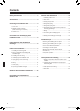
Contents Safety Precautions ..................................... 2 Outdoor Unit Installation ............................ 12 1. Installing outdoor unit .......................................... 12 Accessories ................................................. 4 2. Drain work ............................................................ 12 3. Flaring the pipe end ............................................. 12 Choosing an Installation Site .................... 4 1. Indoor unit ..........................
Safety Precautions Read the precautions in this manual carefully before operating the unit. This appliance is filled with R32. • The precautions described herein are classified as WARNING and CAUTION. They both contain important information regarding safety. Be sure to observe all precautions without fail. • Meaning of WARNING and CAUTION notices WARNING ................... Failure to follow these instructions properly may result in personal injury or loss of life. CAUTION.....................
Safety Precautions WARNING • Be sure to earth the air conditioner. Do not earth the unit to a utility pipe, lightning conductor or telephone earth lead. Imperfect earthing may result in electric shocks. • Be sure to install an earth leakage circuit breaker. Failure to install an earth leakage circuit breaker may result in electric shocks or fire. • Do not use means to accelerate the defrosting process or to clean, other than those recommended by the manufacturer.
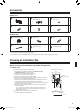
Accessories Indoor unit A B Mounting plate E Wireless remote controller Indoor unit fixing screws (M4 × 12L) 1 1 D C Photocatalytic air-purifying and deodorising filter F Remote controller holder 1 3 Dry batteries AA.LR6 (alkaline) 1 2 Outdoor unit G H Humidifying hose (8m) 1 K J Drain socket Joint 1 1 Binding bands 3 L Operation manual 1 M 1 Installation manual • The standard humidifying hose is 8m. • The extension hose (option) is 2m (KPMH974A402).
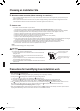
Choosing an Installation Site 2. Wireless remote controller (When mounting on a wall etc.) • Turn on all the fluorescent lamps in the room, if any, and find the site where remote control signals are properly received by the indoor unit (within 7m). • Select a place where the remote controller is not hit by direct sunlight. (Selecting a place where direct sunlight hits the remote controller makes it difficult for the remote controller to receive the signal from the indoor unit.) 3.
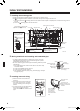
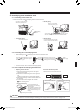
Indoor/Outdoor Unit Installation Drawings How to attach the indoor unit 1) Using the marks (3 locations) on top of the indoor unit, attach the A mounting plate hooks onto the indoor unit. 2) Attach the tabs on the bottom frame onto the A mounting plate. If the tabs are not hooked onto the plate, remove the front grille to hook them. (Check to see if the tabs are hooked securely.
Indoor Unit Installation 1. Installing the mounting plate • The • The A A mounting plate is located at the back of the indoor unit. Remove a screw. mounting plate should be installed on a wall which can support the weight of the indoor unit. 1) Temporarily secure the A mounting plate to the wall, make sure that the plate is completely level, and mark the boring points on the wall. 2) Secure the A mounting plate to the wall with screws. (Bolt size : M10) 72 (Bolt size : M10) 81 251 44 199 14.
4. Humidifying hose installation work 4-1 Connecting to the indoor unit • Connect the cuff side of the humidifying hose to the indoor unit duct. G • Left-side piping It is easier to connect the hose with the front grille removed. Insert as far as possible so that there are no gaps. Duct Cuff G Humidifying hose To pull out the G humidifying hose to the right side, turn the cuff 180° from the position shown in the above illustration.
Indoor Unit Installation 5. Laying piping, hoses, and wiring • Lay the pipes, drain hose and G humidifying hose according to the orientation of the piping coming out of the unit, as shown in the figure. • Make sure the drain hose is sloped downward. • Wrap the pipes, drain hose and G humidifying hose together using insulation tape.
5-3 Wall embedded piping Follow the instructions given under left-side, left-back, or leftbottom piping. 1) Insert the drain hose to this depth so it won’t be pulled out of the drain pipe. Insert drain hose to this depth so it won’t be pulled out of drain pipe. 50mm or more Outer wall Inner wall Drain hose Vinyl chloride drain pipe (VP-30) CAUTION The indoor unit is large, so please be careful not to lose your balance when lifting it. 6. Wiring 1) Strip wire ends (15mm).
Indoor Unit Installation 7. Drain piping 1) Connect the drain hose, as described right. The drain hose should be inclined downward. No trap is permitted. Do not put the end of the hose in water. 2) Remove the air filters and pour some water into the drain pan to check the water flows smoothly. ɸ16 ɸ18 3) If drain hose extension or embedded drain piping is required, use appropriate parts that match the hose front end.
Outdoor Unit Installation Guidelines • Where a wall or other obstacle is in the path of outdoor unit’s intake or exhaust airflow, follow the installation guidelines below. • For any of the below installation patterns, the wall height on the outlet side should be 1200mm or less.
Outdoor Unit Installation 4. Refrigerant piping CAUTION • Use the flare nut fixed to the main unit. (To prevent cracking of the flare nut by aged deterioration.) • To prevent gas leakage, apply refrigeration oil only to the inner surface of the flare. (Use refrigeration oil for R32.) • Use torque wrenches when tightening the flare nuts to prevent damage to the flare nuts and gas leakage. • Align the centres of both flares and tighten the flare nuts 3 or 4 turns by hand.
6. Evacuating the air with a vacuum pump and checking gas leakage WARNING • • • • Do not mix any substance other than the specified refrigerant (R32) into the refrigeration cycle. When refrigerant gas leaks occur, ventilate the room as soon and as much as possible. R32, as well as other refrigerants, should always be recovered and never be released directly into the environment. Use tools for R32 or R410A (such as the gauge manifold, charging hose, or vacuum pump adapter).
Outdoor Unit Installation 7. Wiring WARNING • Do not use tapped wires, extension cords, or starburst connections, as they may cause overheating, electrical shock, or fire. • Do not use locally purchased electrical parts inside the product. (Do not branch the power for the drain pump, etc., from the terminal block.) Doing so may cause electric shock or fire. • Be sure to install an earth leak detector. (One that can handle higher harmonics.
8. Connecting the humidifying hose • If the air conditioner is operated without the G humidifying hose connected, humidified air fills the outdoor unit and may cause a short-circuit on the printed circuit board. Be sure to connect it. 1) Connect the G humidifying hose to the outdoor humidifying duct. 2) Apply a K binding band to prevent the G humidifying hose from coming off. Outdoor humidifying duct Section B Attach the G humidifying hose, making sure there is no gap.
Installation Tips Removing and installing the front panel • Removal method 1) Hook your fingers on both sides of the front panel and open until the panel stops. Pushing further up from the stopping position allows the panel to be removed more easily. 2) While pushing the left side front panel shaft outward, push up the front panel and remove it. (Remove the right side front panel shaft in the same manner.) 3) After removing both front panel shafts, pull the front panel toward yourself and remove it.
• Installation method Fig. 8 1) Attach the front grille (bottom). Make sure that the tabs on both sides are securely hooked. (See Fig. 8) 2) Attach the service lid and secure it with a screw. 3) Attach the screw cover. 4) Attach the front grilles (left and right) and tighten the mounting screws (2 screws for the left side, 3 for the right side). The front grilles (left and right) are likely to override the front grille (bottom). Pay due caution when attaching them. (See Fig. 9) Fig.
Trial Operation and Testing 1. Setting of the position where the indoor unit is installed • By setting the room shape and the relation with the installation position, proper airflow direction control can be obtained. If this is not set correctly, proper indoor temperature control may not be provided depending on the airflow settings. 1) Press For details, refer to the operation manual. Left corner for 20 to 500mm Right corner for 20 to 500mm Centre for installation in the centre .
3-3 To perform a trial operation for humidifying operation, activate trial operation mode from the remote controller following the instructions below and press Trial operation from remote controller 1) Press 2) Press for at least 5 seconds. (The default menu will be displayed.) to select “Test mode” and press • The unit enters trial operation mode, and . is displayed on the screen. 3) Press the button for the operation mode (COOLING/HEATING/HUMIDFY) you want to test.
Two-dimensional bar code is a code for manufacturing. 3P338604-1C M12B406B (1310) 00_CV_3P338604-1C.