
Installation manual

Refrigerant Piping Work
2. Refrigerant piping.
2-1. Caution on piping handling.
1) Protect the open end of the pipe against dust and moisture.
2) All pipe bends should be as gentle as possible. Use a
pipe bender for bending.
2-2. Selection of copper and heat insulation materials.
•
When using commercial copper pipes and fittings, observe the following:
1) Insulation material: Polyethylene foam
Heat transfer rate: 0.041 to 0.052W/mK (0.035 to 0.045kcal/(mh •˚C))
Refrigerant gas pipe’s surface temperature reaches 110˚C max.
Choose heat insulation materials that will withstand this temperature.
2) Be sure to insulate both the gas and liquid piping and to provide insulation dimensions as below.
1. Flaring the pipe end.
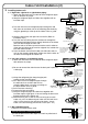
1) Cut the pipe end with a pipe cutter.
2)
Remove burrs with the cut surface facing
downward so that the chips do not enter the
pipe.
3) Put the flare nut on the pipe.
4) Flare the pipe.
5) Check that the flaring is properly made.
1) Do not use mineral oil on flared part.
2) Prevent mineral oil from getting into the system as this would reduce the lifetime of the units.
3)
Never use piping which has been used for previous installations. Only use parts which are delivered with the unit.
4) Do never install a drier to this R410A unit in order to guarantee it’s lifetime.
5) The drying material may dissolve and damage the system.
6) Incomplete flaring may cause refrigerant gas leakage.
WARNING
3) Use separate thermal insulation pipes for gas and liquid refrigerant pipes.
Thickness 10mm Min.
71/80/90 class
O.D. 15.9mm
50mm or more
Thickness 1.0mm
(C1220T-O)
50/60 class
O.D. 12.7mm
40mm or more
Thickness 0.8mm
(C1220T-O)
71/80/90 class
I.D. 16-20mm
50/60 class
I.D. 14-16mm
Gas side
Minimum bend radius
Gas pipe thermal insulation
50/60/71/80/90 classs
O.D. 6.4mm
30mm or more
Thickness 0.8mm
(C1220T-O)
50/60/71/80/90 class
I.D. 8-10mm
Liquid side
Liquid pipe thermal insulation
Flare nut tightening torque
Gas side Liquid side
1/2 inch
49.5-60.3N m
(505-615kgf cm)
61.8-75.4N m
(630-770kgf cm)
14.2-17.2N m
(144-175kgf cm)
5/8 inch 1/4 inch
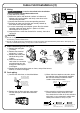
1) Use the flare nut fixed to the main unit. (To prevent cracking of the flare nut by aged deterioration.)
2)
To prevent gas leakage, apply refrigeration oil only to the inner surface of the flare. (Use refrigeration oil for R410A.)
3)
Use torque wrenches when tightening the flare nuts to prevent damage to the flare nuts and gas leakage.
Align the centres of both flares and tighten the flare nuts 3 or 4 turns by hand. Then tighten them fully with the torque wrenches.
CAUTION
Torque wrench
Piping union
Flare nut
Do not apply refrigeration
oil to the outer surface.
Flare nut
Apply refrigeration oil to the
inner surface of the flare.
Do not apply
refrigeration oil to the
flare nut avoid tightening
with over torque.
Spanner
[Apply oil] [Tighten]
,
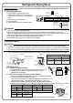
install as described in the installation manual supplied with the Multi outdoor unit.
With a Multi indoor unit
Wall
If no flare cap is
available, cover
the flare mouth
with tape to keep
dirt or water out.
Be sure to
place a cap.
Rain
Gas pipe
Liquid pipe
Gas pipe
insulation
Liquid pipe
insulation
Finishing tape
Drain hose
Inter-unit wiring
(Cut exactly at
right angles.) Remove burrs
Set exactly at the position shown below.
A
Flaring
Die
A 0-0.5mm
Clutch-type
Flare tool for R410A
1.0-1.5mm
Clutch-type (Rigid-type)
1.5-2.0mm
Wing-nut type (Imperial-type)
Conventional flare tool
Check
Flare’s inner
surface must
be flaw-free.
The pipe end must
be evenly flared in
a perfect circle.
Make sure that the
flare nut is fitted.