
Service manual
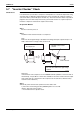

Check SiBE041134
102 Service Diagnosis
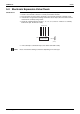
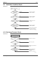
5.2 Fan Motor Connector Output Check
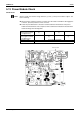
Check No.03 Fan motor wire breakdown / short circuit check
1. Check the connector for connection.
2. Turn the power off.
3. Check if each resistance at the phases U - V and V - W is 90
Ω ~ 100 Ω (between the pins
12 - 9, and between 9 - 6).
Motor control voltage check
1. Check the connector for connection.
2. Check the motor control voltage is generated (between the pins 2 - 3).
Rotation pulse check
1. Check the connector for connection.
2. Turn the power on and stop the operation.
3. Check if the Hall IC generates the rotation pulse 4 times when the fan motor is manually
rotated once (between the pins 1 - 3).
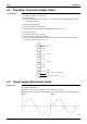
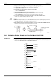
5.3 Power Supply Waveforms Check
Check No.11 Measure the power supply waveform between No. 1 and No. 2 on the terminal board, and check
the waveform disturbance.
Check to see if the power supply waveform is a sine wave. (Fig.1)
Check to see if there is waveform disturbance near the zero cross. (sections circled in Fig.2)
(R11979)
12
11
10
9
8
7
6
5
4
3
2
1
Phase U
Free pin
Free pin
Free pin
Free pin
Free pin
Free pin
Phase V
Phase W
GND
Motor control voltage (15 VDC)
Rotation pulse (5 VDC)
S200
Fig.1 Fig.2