SiBE041134 Service Manual Inverter Pair Wall Mounted Type K-Series [Applied Models] z Inverter Pair : Heat Pump
SiBE041134 Inverter Pair Wall Mounted Type K-Series zHeat Pump Indoor Unit FTXS20K2V1B FTXS25K2V1B Outdoor Unit RXS20K2V1B RXS25K2V1B i Table of Contents
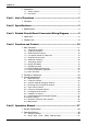
SiBE041134 1. Introduction .............................................................................................v 1.1 Safety Cautions ........................................................................................v 1.2 Used Icons .............................................................................................. ix Part 1 List of Functions ................................................................ 1 1. Functions.............................................................
SiBE041134 2.3 2.4 2.5 2.6 2.7 2.8 2.9 2.10 2.11 Adjusting the Airflow Direction and Rate ................................................43 COMFORT AIRFLOW Operation ...........................................................45 INTELLIGENT EYE Operation ...............................................................46 POWERFUL Operation ..........................................................................48 OUTDOOR UNIT QUIET Operation.......................................................
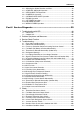
SiBE041134 5.10 5.11 5.12 5.13 Discharge Pressure Check...................................................................107 Outdoor Fan System Check .................................................................108 Main Circuit Short Check......................................................................108 Power Module Check ...........................................................................109 Part 7 Removal Procedure ........................................................ 110 1.
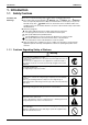
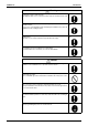
Introduction SiBE041134 1. Introduction 1.1 Safety Cautions Cautions and Warnings Be sure to read the following safety cautions before conducting repair work. The caution items are classified into “ Warning” and “ Caution”. The “ Warning” items are especially important since they can lead to death or serious injury if they are not followed closely. The “ Caution” items can also lead to serious accidents under some conditions if they are not followed.
SiBE041134 Introduction Warning Be sure to wear a safety helmet, gloves, and a safety belt when working at a high place (more than 2 m). Insufficient safety measures may cause a fall accident. In case of R-410A refrigerant models, be sure to use pipes, flare nuts and tools for the exclusive use of the R-410A refrigerant. The use of materials for R-22 refrigerant models may cause a serious accident such as a damage of refrigerant cycle as well as an equipment failure.
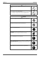
Introduction SiBE041134 1.1.2 Cautions Regarding Safety of Users Warning Be sure to use parts listed in the service parts list of the applicable model and appropriate tools to conduct repair work. Never attempt to modify the equipment. The use of inappropriate parts or tools may cause an electrical shock, excessive heat generation or fire. If the power cable and lead wires have scratches or deteriorated, be sure to replace them.
SiBE041134 Introduction Warning Check to make sure that the power cable plug is not dirty or loose, then insert the plug into a power outlet securely. If the plug has dust or loose connection, it may cause an electrical shock or fire. Be sure to install the product correctly by using the provided standard For unitary type installation frame. only Incorrect use of the installation frame and improper installation may cause the equipment to fall, resulting in injury.
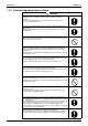
Introduction SiBE041134 Caution Be sure to measure the insulation resistance after the repair, and make sure that the resistance is 1 MΩ or higher. Faulty insulation may cause an electrical shock. Be sure to check the drainage of the indoor unit after the repair. Faulty drainage may cause the water to enter the room and wet the furniture and floor. Do not tilt the unit when removing it. The water inside the unit may spill and wet the furniture and floor.
SiBE041134 Part 1 List of Functions 1. Functions.................................................................................................
Functions SiBE041134 Basic Function Functions Inverter (with Inverter Power Control) Operation Limit for Cooling (°CDB) Operation Limit for Heating (°CWB) Compressor Comfortable Airflow Comfort Control Operation Lifestyle Convenience Health & Clean –15 ~ 18 Functions Air-Purifying Filter — Photocatalytic Deodorizing Filter — Air-Purifying Filter with Photocatalytic Deodorizing Function — PAM Control z Standby Electricity Saving z Titanium Apatite Photocatalytic Air-Purifying Filter z
SiBE041134 Part 2 Specifications 1. Specifications ..........................................................................................
Specifications SiBE041134 1. Specifications 50 Hz, 220 - 230 - 240 V Indoor Unit Model FTXS20K2V1B RXS20K2V1B Outdoor Unit Capacity Rated (Min. ~ Max.) Running Current (Rated) Power Consumption Rated (Min. ~ Max.) Power Factor COP (Rated) Liquid Piping Connections Gas Drain Heat Insulation Max. lnterunit Piping Length Max.
SiBE041134 Part 3 Printed Circuit Board Connector Wiring Diagram 1. Indoor Unit...............................................................................................6 2. Outdoor Unit............................................................................................
Indoor Unit SiBE041134 1.
SiBE041134 PCB Detail Indoor Unit PCB(1): Control PCB S32 S26 S6 JA JC JB LED A S25 S200 S403 FU1 V1 H1 FG1, FG2 H3 H2 2P297453-1 PCB(2): Display PCB S27 SW1 LED3 LED2 LED1 (Solder side) RTH1 3P185701-3 PCB(3): INTELLIGENT EYE Sensor PCB S36 3P296737-1 Printed Circuit Board Connector Wiring Diagram 7
Outdoor Unit SiBE041134 2. Outdoor Unit Connectors and Other Parts PCB (1): Filter PCB 1) 2) 3) 4) 5) 6) 7) 8) S11 AC1, AC2, S E1, E2 HL2, HN2 HR1 FU1 FU3 V2, V3 Connector for main PCB Connector for terminal board Terminal for ground wire Connector for main PCB Connector for reactor Fuse (3.
SiBE041134 PCB Detail Outdoor Unit PCB (1): Filter PCB HR1 E1, E2 HN2 V2 AC2 AC1 V3 S11 FU3 S FU1 HL2 S50 (on main PCB) 3P254234-1 PCB (2): Main PCB U VW S10 J5 J4 S90 LED A S70 S40 HR2 S20 S80 HL3 V1 HN3 FU2 S100 S50 2P254206-1 PCB (3): Forced Operation Button PCB SW1 S110 3P255755-1 Printed Circuit Board Connector Wiring Diagram 9
SiBE041134 Part 4 Function and Control 1. Main Functions......................................................................................11 1.1 1.2 1.3 1.4 1.5 1.6 1.7 1.8 1.9 1.10 1.11 1.12 Temperature Control ..............................................................................11 Frequency Principle................................................................................11 Airflow Direction Control.........................................................................
SiBE041134 Main Functions 1. Main Functions 1.1 Temperature Control Definitions of Temperatures The definitions of temperatures are classified as following.
Main Functions Drawing of Inverter SiBE041134 The following drawing shows a schematic view of the inverter principle: Refrigerant circulation rate (high) AC power Amount of heat exchanged air (small) DC power high speed Amount of heat exchanged air (large) high f low f low speed 50 Hz freq= constant 60 Hz freq=variable Amount of heat exchanged air (large) Amount of heat exchanged air (small) capacity= variable Refrigerant circulation rate (low) (R2812) Inverter Features The inverter provides
SiBE041134 1.3 Main Functions Airflow Direction Control Power-Airflow Dual Flap The large flap sends a large volume of air downward to the floor and provides an optimum control in cooling, dry, and heating operation. During cooling or dry operation, the flap retracts into the indoor unit. Then, cool air can be blown far and distributed all over the room. During heating operation, the large flap directs airflow downward to spread the warm air to the entire room.
Main Functions 1.4 SiBE041134 Fan Speed Control for Indoor Unit Outline Phase control and fan speed control contains 9 steps: LLL, LL, SL, L, ML, M, MH, H, and HH. The airflow rate can be automatically controlled depending on the difference between the room thermistor temperature and the target temperature. This is done through phase control and Hall IC control. For more information about Hall IC, refer to the troubleshooting for fan motor on page 70.
SiBE041134 1.5 Main Functions Program Dry Operation Outline Program dry operation removes humidity while preventing the room temperature from lowering. Since the microcomputer controls both the temperature and airflow rate, the temperature adjustment and [FAN] setting buttons are inoperable. Detail The microcomputer automatically sets the temperature and airflow rate. The difference between the room thermistor temperature at start-up and the target temperature is divided into two zones.
Main Functions 1.6 Outline Detail SiBE041134 Automatic Operation Automatic Cooling / Heating Function When the automatic operation is selected with the remote controller, the microcomputer automatically determines the operation mode as cooling or heating according to the room temperature and the set temperature at start-up. The unit automatically switches the operation mode to maintain the room temperature at the set temperature.
SiBE041134 1.7 Main Functions Thermostat Control Thermostat control is based on the difference between the room thermistor temperature and the target temperature. Thermostat OFF Condition The temperature difference is in the zone A. Thermostat ON Condition The temperature difference returns to the zone C after being in the zone A. The system resumes from defrost control in any zones except A. The operation turns on in any zones except A.
Main Functions 1.8 SiBE041134 NIGHT SET Mode Outline When the OFF TIMER is set, the NIGHT SET Mode is automatically activated. The NIGHT SET Mode keeps the airflow rate setting. Detail The NIGHT SET Mode continues operation at the target temperature for the first one hour, then automatically raises the target temperature slightly in the case of cooling, or lowers it slightly in the case of heating.
SiBE041134 1.9 Main Functions ECONO Operation Outline ECONO operation reduces the maximum operating current and the power consumption. This operation is particularly convenient for energy-saving-oriented users. It is also a major bonus for those whose breaker capacities do not allow the use of multiple electrical devices and air conditioners. It is easily activated from the wireless remote controller by pushing the [ECONO] button. When this function is activated, the maximum capacity also decreases.
Main Functions SiBE041134 1.10 INTELLIGENT EYE Operation Outline This function detects the existence of humans in the room with a motion sensor (INTELLIGENT EYE) and reduces the capacity when there is nobody in the room in order to save electricity. Detail 1. Detection method by INTELLIGENT EYE sampling (20 msec.) Sensor output If the sensor detects the outputs 10 times/sec. or more, it judges humans exist. 1 sec.
SiBE041134 Main Functions 1.11 Inverter POWERFUL Operation Outline In order to exploit the cooling and heating capacity to full extent, operate the air conditioner by increasing the indoor fan rotating speed and the compressor frequency. Detail When the [POWERFUL] button is pressed, the fan speed and target temperature are converted to the following states for 20 minutes.
Main Functions SiBE041134 1.12 Other Functions 1.12.1 Hot-Start Function In order to prevent the cold air blast that normally comes when heating operation is started, the temperature of the indoor heat exchanger is detected, and the airflow is either stopped or made very weak thereby carrying out comfortable heating of the room. *The cold air blast is also prevented using similar control when the defrosting operation is started or when the thermostat is turned ON. 1.12.
SiBE041134 Function of Thermistor 2. Function of Thermistor Electronic expansion valve (1) (3) Four way valve (2) Compressor (R14247) (1) Outdoor Heat Exchanger Thermistor 1. The outdoor heat exchanger thermistor is used for controlling the target discharge pipe temperature.
Control Specification SiBE041134 3. Control Specification 3.1 Mode Hierarchy Outline There are 3 modes; normal operation mode, forced operation mode and the power transistor test mode for installation and servicing.
SiBE041134 3.2 Control Specification Frequency Control Outline Frequency is determined according to the difference between the room thermistor temperature and the target temperature. The function is explained as follows. 1. How to determine frequency 2. Frequency command from the indoor unit (Difference between the room thermistor temperature and the target temperature) 3. Frequency initial setting 4.
Control Specification SiBE041134 Indoor Frequency Command (∆D signal) The difference between the room thermistor temperature and the target temperature is taken as the “∆D signal” and is used for frequency command. Temperature difference –2.0 ∆D signal ∗Th OFF Temperature difference 0 ∆D signal 4 Temperature difference 2.0 ∆D signal 8 Temperature difference 4.0 ∆D signal C –1.5 –1.0 1 2 0.5 1.0 5 6 2.5 3.0 9 A 4.5 5.0 D E –0.5 3 1.5 7 3.5 B 5.
SiBE041134 3.3 Control Specification Controls at Mode Changing / Start-up 3.3.1 Preheating Operation Outline The inverter operation in open phase starts with the conditions of the preheating command from the indoor unit, the outdoor temperature, and the discharge pipe temperature.
Control Specification SiBE041134 3.3.5 Compressor Protection Function When turning the compressor from OFF to ON, the upper limit of frequency is set as follows. (The function is not activated when defrosting.) (Hz) Frequency C B A D E (sec.) Time F (R13528) 3.4 Outline A (Hz) 48 B (Hz) C (Hz) 64 88 D (seconds) E (seconds) 240 360 F (seconds) 180 Discharge Pipe Temperature Control The discharge pipe temperature is used as the internal temperature of the compressor.
SiBE041134 3.5 Control Specification Input Current Control Outline The microcomputer calculates the input current while the compressor is running, and sets the frequency upper limit from the input current. In case of heat pump models, this control which is the upper limit control of the frequency takes priority over the lower limit of control of four way valve operation compensation.
Control Specification 3.6 SiBE041134 Freeze-up Protection Control Outline During cooling operation, the signal sent from the indoor unit controls the operating frequency limitation and prevents freezing of the indoor heat exchanger. (The signal from the indoor unit is divided into zones.) Detail The operating frequency limitation is judged with the indoor heat exchanger temperature.
SiBE041134 3.8 Control Specification Outdoor Fan Control 1. Fan ON control to cool down the electrical box The outdoor fan is turned ON when the electrical box temperature is high while the compressor is OFF. 2. Fan OFF control during defrosting The outdoor fan is turned OFF during defrosting. 3. Fan OFF delay when stopped The outdoor fan is turned OFF 60 seconds after the compressor stops. 4.
Control Specification SiBE041134 3.10 Defrost Control Outline Defrosting is carried out by the cooling cycle (reverse cycle). The defrosting time or outdoor heat exchanger temperature must be more than a certain value to finish. Detail Conditions for Starting Defrost The starting conditions are determined with the outdoor temperature and the outdoor heat exchanger temperature. The system is in heating operation. The compressor operates for 6 minutes.
SiBE041134 Control Specification 3.11 Electronic Expansion Valve Control During target discharge pipe temperature control When the frequency changes under target discharge pipe temperature control When the disconnection of the discharge pipe thermistor is ascertained When the frequency changes under the control for disconnection of the discharge pipe thermistor Under defrost control The followings are the examples of electronic expansion valve control which function in each operation mode.
Control Specification SiBE041134 3.11.1 Fully Closing with Power ON The electronic expansion valve is initialized when turning on the power. The opening position is set and the pressure equalization is developed. 3.11.2 Pressure Equalizing Control When the compressor is stopped, the pressure equalization control is activated. The electronic expansion valve opens, and develops the pressure equalization. 3.11.
SiBE041134 Control Specification 3.11.7 Control for Disconnection of the Discharge Pipe Thermistor Outline The disconnection of the discharge pipe thermistor is detected by comparing the discharge pipe temperature with the condensation temperature. If the discharge pipe thermistor is disconnected, the electronic expansion valve opens according to the outdoor temperature and the operation frequency, operates for a specified time, and then stops.
Control Specification SiBE041134 3.12 Malfunctions 3.12.1 Sensor Malfunction Detection Sensor malfunction may occur in the thermistor. Relating to Thermistor Malfunction 1. Outdoor heat exchanger thermistor 2. Discharge pipe thermistor 3. Radiation fin thermistor 4. Outdoor temperature thermistor 3.12.2 Detection of Overcurrent and Overload Outline An excessive output current is detected and the OL temperature is observed to protect the compressor.
SiBE041134 Part 5 Operation Manual 1. System Configuration............................................................................38 2. Operation Manual..................................................................................39 2.1 2.2 2.3 2.4 2.5 2.6 2.7 2.8 2.9 2.10 2.11 Operation Manual Remote Controller ..................................................................................39 AUTO · DRY · COOL · HEAT · FAN Operation ......................................
System Configuration SiBE041134 1. System Configuration After installation and trial operation of the room air conditioner are completed, the air conditioner should be handled and operated as described in the following pages. Every user should be informed on the correct method of operation and how to check if it can cool (or heat) well, and how to use it efficiently. Providing instructions to the user can reduce requests for servicing by 80%.
SiBE041134 Operation Manual 2. Operation Manual 2.1 Remote Controller Name of Parts Remote Controller Signal transmitter Receiver Display (LCD) • It displays the current settings. (In this illustration, each section is shown with its displays on for the purpose of explanation.) • To use the remote controller, aim the transmitter at the indoor unit. If there is anything to block signals between the unit and the remote controller, such as a curtain, the unit will not operate.
Operation Manual SiBE041134 Open the front cover MODE selector button • It selects the operation mode. (AUTO/DRY/COOL/HEAT/ FAN) Page 11 ECONO button • ECONO operation. Page 20 SWING button • Adjusting the airflow direction. Page 13 QUIET button • OUTDOOR UNIT QUIET operation. Page 19 INTELLIGENT EYE button COMFORT button • INTELLIGENT EYE operation. Page 16 • COMFORT AIRFLOW operation.
SiBE041134 2.2 Operation Manual AUTO · DRY · COOL · HEAT · FAN Operation AUTO · DRY · COOL · HEAT · FAN Operation The air conditioner operates with the operation mode of your choice. From the next time on, the air conditioner will operate with the same operation mode. To start operation 1. Press and select an operation mode. • Each pressing of the button advances the mode setting in sequence. AUTO 2. Press DRY COOL HEAT FAN . •“ ” is displayed on the LCD. • The OPERATION lamp lights green.
Operation Manual SiBE041134 To change the temperature setting Press . • The displayed items on the LCD will change whenever either one of the buttons is pressed. COOL operation HEAT operation AUTO operation 18-32˚C 10-30˚C 18-30˚C Press to raise the temperature and press temperature. to lower the DRY or FAN operation The temperature setting is not variable.
SiBE041134 2.3 Operation Manual Adjusting the Airflow Direction and Rate Adjusting the Airflow Direction and Rate You can adjust the airflow direction to increase your comfort. To start auto swing Upper and lower airflow direction Press . • “ ” is displayed on the LCD. • The flap (horizontal blade) will begin to swing. To set the flap at desired position • This function is effective while flap is in auto swing mode. Press when the flap has reached the desired position.
Operation Manual SiBE041134 To adjust the airflow rate setting Press . • Each pressing of advances the airflow rate setting in sequence. Indoor unit quiet Auto High Middle high Low Middle low Middle • When the airflow is set to “ ”, indoor unit quiet operation will start and the noise from the unit will become quieter. • In indoor unit quiet operation, the airflow rate is set to a weak level.
SiBE041134 2.4 Operation Manual COMFORT AIRFLOW Operation COMFORT AIRFLOW Operation The flow of air will be in the upward direction while in COOL operation and in the downward direction while in HEAT operation, which will provide a comfortable wind that will not come in direct contact with people. To start COMFORT AIRFLOW operation Press . • “ ” is displayed on the LCD. • Airflow rate is set to Auto. COOL/DRY: The flap will go up. HEAT: The flap will go down.
Operation Manual 2.5 SiBE041134 INTELLIGENT EYE Operation INTELLIGENT EYE Operation “INTELLIGENT EYE” is the infrared sensor which detects the human movement. If nobody in the room for more than 20 minutes, the operation automatically changes to energy saving operation. To start INTELLIGENT EYE operation Press . •“ ” is displayed on the LCD. • The INTELLIGENT EYE lamp lights green. Display To cancel INTELLIGENT EYE operation Press again. •“ ” disappears from the LCD.
SiBE041134 Operation Manual INTELLIGENT EYE Operation [Example] When someone is in the room When no one is in the room 20 minutes after, start energy saving operation. Normal operation • The air conditioner is in normal operation while the sensor is detecting the movement of people. Someone is back in the room Back to normal operation. • The set temperature is shifted in ±2˚C steps. • The air conditioner will return to normal operation when the sensor detects the movement of people again.
Operation Manual 2.6 SiBE041134 POWERFUL Operation POWERFUL Operation POWERFUL operation quickly maximizes the cooling (heating) effect in any operation modes. You can get the maximum capacity. To start POWERFUL operation Press during operation. • POWERFUL operation ends in 20 minutes. Then the system automatically operates again with the previous settings which were used before POWERFUL operation. •“ ” is displayed on the LCD. To cancel POWERFUL operation Press •“ again.
SiBE041134 2.7 Operation Manual OUTDOOR UNIT QUIET Operation OUTDOOR UNIT QUIET Operation OUTDOOR UNIT QUIET operation lowers the noise level of the outdoor unit by changing the frequency and fan speed on the outdoor unit. This function is convenient during the night. To start OUTDOOR UNIT QUIET operation Press •“ . ” is displayed on the LCD. To cancel OUTDOOR UNIT QUIET operation Press •“ [Example] again. ” disappears from the LCD. Using the OUTDOOR UNIT QUIET operation during the night.
Operation Manual 2.8 SiBE041134 ECONO Operation ECONO Operation ECONO operation is a function which enables efficient operation by limiting the maximum power consumption value. This function is useful for cases in which attention should be paid to ensure a circuit breaker will not trip when the product runs alongside other appliances. To start ECONO operation Press •“ during operation. ” is displayed on the LCD. To cancel ECONO operation Press •“ again. ” disappears from the LCD.
SiBE041134 2.9 Operation Manual OFF TIMER Operation OFF TIMER Operation Timer functions are useful for automatically switching the air conditioner on or off at night or in the morning. You can also use OFF TIMER and ON TIMER in combination. To use OFF TIMER operation • Check that the clock is correct. If not, set the clock to the present time. 1. Press . •“ •“ •“ ” is displayed on the LCD. ” blinks. ” and day of the week disappear from the LCD. 2.
Operation Manual SiBE041134 2.10 ON TIMER Operation ON TIMER Operation To use ON TIMER operation • Check that the clock is correct. If not, set the clock to the present time. 1. Press . •“ •“ •“ ” is displayed on the LCD. ” blinks. ” and day of the week disappear from the LCD. 2. Press until the time setting reaches the point you like. • Each pressing of either button increases or decreases the time setting by 10 minutes. Holding down either button changes the setting rapidly. 3. Press again.
SiBE041134 Operation Manual 2.11 WEEKLY TIMER Operation WEEKLY TIMER Operation Up to 4 timer settings can be saved for each day of the week. It is convenient if the WEEKLY TIMER is set according to the family’s life style. Using in these cases of WEEKLY TIMER Example: The same timer settings are made for the week from Monday through Friday while different timer settings are made for the weekend. [Monday] Make timer settings up to programs 1-4.
Operation Manual SiBE041134 To use WEEKLY TIMER operation Setting mode • Make sure the day of the week and time are set. If not, set the day of the week and time. Program 1 Program 2 Program 3 Program 4 ON OFF ON OFF 8:30 17:30 [Monday] 27°C 25°C 6:00 22:00 Setting Displays Day and number 1. Press ON/OFF Time Temperature . • The day of the week and the reservation number of the current day will be displayed. • 1 to 4 settings can be made per day. 2.
SiBE041134 Operation Manual WEEKLY TIMER Operation 6. Press to select the desired time. • The time can be set between 0:00 and 23:50 in 10 minute intervals. • To return to the ON/OFF TIMER mode setting, press • Go to step 9 when setting the OFF TIMER. 7. Press . . • The time will be set. •“ ” and the temperature blink. 8. Press to select the desired temperature. • The temperature can be set between 10˚C and 32˚C. COOL or AUTO: The unit operates at 18˚C even if it is set at 10 to 17˚C.
Operation Manual SiBE041134 Copy mode • A reservation made once can be copied to another day of the week. The whole reservation of the selected day of the week will be copied. Program 1 ON [Monday] [Tuesday] to [Friday] Program 2 OFF Program 3 ON 27°C 25°C 6:00 8:30 Program 1 ON Program 2 OFF 17:30 22:00 Program 3 ON Program 4 OFF 27°C 25°C 6:00 Program 4 OFF 8:30 17:30 22:00 Setting Displays Confirmation Copy Paste Normal 1. Press . 2.
SiBE041134 Operation Manual WEEKLY TIMER Operation Confirming a reservation • The reservation can be confirmed. Setting Displays Normal 1. Press Confirmation . • The day of the week and the reservation number of the current day will be displayed. 2. Press to select the day of the week and the reservation number to be confirmed. • Pressing displays the reservation details. • To change the confirmed reserved settings, select the reservation number and press .
Operation Manual SiBE041134 To delete reservations The individual reservation 1. Press . • The day of the week and the reservation number will be displayed. 2. Press to select the day of the week and the reservation number to be deleted. 3. Press •“ . ” and “ 4. Press • Pressing ” or “ ” blink. and select “blank ”. changes ON/OFF TIMER mode. Pressing alternates the following items appearing on the LCD in rotational sequence. • The reservation will be no setting with selecting “blank”.
SiBE041134 Part 6 Service Diagnosis 1. Troubleshooting with LED .....................................................................60 1.1 Indoor Unit..............................................................................................60 1.2 Outdoor Unit ...........................................................................................60 2. Problem Symptoms and Measures .......................................................61 3. Service Check Function ..................................
Troubleshooting with LED SiBE041134 1. Troubleshooting with LED 1.1 Indoor Unit Operation Lamp The operation lamp blinks when any of the following errors is detected. 1. When a protection device of the indoor or outdoor unit is activated, or when the thermistor malfunctions. 2. When a signal transmission error occurs between the indoor and outdoor units. In either case, conduct the diagnostic procedure described in the following pages. Operation lamp (green) Service Monitor 1.
SiBE041134 Problem Symptoms and Measures 2. Problem Symptoms and Measures Symptom Check Item The unit does not operate. Check the power supply. Check the type of the indoor unit. Check the outdoor temperature. Diagnose with remote controller indication. Check the remote controller addresses. Operation sometimes stops. Check the power supply. Check the outdoor temperature. Diagnose with remote controller indication.
Service Check Function SiBE041134 3. Service Check Function Check Method 1 1. When the timer cancel button is held down for 5 seconds, 00 is displayed on the temperature display screen. Timer cancel button (R14553) < ARC466 Series > 2. Press the timer cancel button repeatedly until a long beep sounds. The code indication changes in the sequence shown below. Note: 62 No. 1 Code 00 No. 13 Code C7 No.
SiBE041134 Service Check Function Check Method 2 1. Press the center of the [Temp] button and the [Mode] button at the same time. (R11669) 5C is displayed on the LCD. (R11821) 2. Select 5C (service check) with the [Temp] or button. 3. Press the [Mode] button to enter the service check mode. (R11672) The left-side number blinks. (R11670) 4. Press the [Temp] or button and change the number until you hear the two consecutive beeps or the long beep.
Service Check Function SiBE041134 5. Diagnose by the sound. beep : The left-side number does not correspond with the error code. two consecutive beeps : The left-side number corresponds with the error code but the right-side number does not. long beep : Both the left-side and right-side numbers correspond with the error code. (The numbers indicated when you hear the long beep are the error code. → Refer to page 65.) 6. Press the [Mode] button. (R11672) The right-side number blinks. (R11673) 7.
SiBE041134 Troubleshooting 4. Troubleshooting 4.
Troubleshooting 4.2 SiBE041134 Indoor Unit PCB Abnormality Remote Controller Display A1 Method of Malfunction Detection The system checks if the circuit works properly within the microcomputer of the indoor unit. Malfunction Decision Conditions The system cannot set the internal settings.
SiBE041134 Troubleshooting Troubleshooting Be sure to turn off the power switch before connecting or disconnecting connectors, or parts may be damaged. Caution Check the combination of the indoor and outdoor unit. OK? NO Match the compatible models. YES Check the connection of connectors (See Note.). OK? ∗ To secure the connection, once disconnect the connector and then reconnect it. YES Check the power supply voltage. NO Voltage as rated? NO Correct the power supply. YES Start operation.
Troubleshooting 4.3 SiBE041134 Freeze-up Protection Control or Heating Peak-cut Control Remote Controller Display A5 Method of Malfunction Detection Freeze-up protection control During cooling operation, the freeze-up protection control (operation halt) is activated according to the temperature detected by the indoor heat exchanger thermistor.
SiBE041134 Troubleshooting Troubleshooting Be sure to turn off the power switch before connecting or disconnecting connectors, or parts may be damaged. Caution Check No.01 Refer to P.101 Check the air passage. Is there any short circuit? YES Provide sufficient air passage. NO Check the air filter. Dirty? Is it very dirty? YES Clean the air filter. NO Check the dust accumulation on the indoor heat exchanger. Dirty? Is it very dirty? YES Clean the indoor heat exchanger. NO Check Check No. No.
Troubleshooting 4.4 SiBE041134 Fan Motor (DC Motor) or Related Abnormality Remote Controller Display A6 Method of Malfunction Detection The rotation speed detected by the Hall IC during fan motor operation is used to determine abnormal fan motor operation. Malfunction Decision Conditions The detected rotation speed does not reach the demanded rotation speed of the target tap, and is less than 50% of the maximum fan motor rotation speed.
SiBE041134 Troubleshooting Troubleshooting Caution Check No.03 Refer to P.102 Be sure to turn off the power switch before connecting or disconnecting connectors, or parts may be damaged. Turn off the power. (Unplug the power cable or turn the breaker OFF.) Note: The motor may break when the motor connector is disconnected while remaining power supply. (Turn off the power supply before connecting the connector also.) Check the connector for connection.
Troubleshooting 4.5 SiBE041134 Thermistor or Related Abnormality (Indoor Unit) Remote Controller Display C4, C9 Method of Malfunction Detection The temperatures detected by the thermistors determine thermistor errors. Malfunction Decision Conditions The thermistor input is more than 4.96 V or less than 0.04 V during compressor operation. Supposed Causes Disconnection of connector Defective thermistor Defective indoor unit PCB Troubleshooting Caution Check No.01 Refer to P.
SiBE041134 4.6 Troubleshooting Refrigerant Shortage Remote Controller Display Method of Malfunction Detection U0 Refrigerant shortage detection I: Refrigerant shortage is detected by checking the input current value and the compressor running frequency. If the refrigerant is short, the input current is lower than the normal value. Refrigerant shortage detection II: Refrigerant shortage is detected by checking the discharge pipe temperature and the opening of the electronic expansion valve.
Troubleshooting SiBE041134 Troubleshooting Caution Check No.01 Refer to P.101 Be sure to turn off the power switch before connecting or disconnecting connectors, or parts may be damaged. Any thermistor disconnected? NO Check No.12 Refer to P.103 Stop valve closed? YES ∗ Discharge pipe thermistor ∗ Indoor or outdoor heat exchanger thermistor ∗ Room temperature thermistor ∗ Outdoor temperature thermistor YES Replace the thermistor(s) in position. Open the stop valve.
SiBE041134 4.7 Troubleshooting Low-voltage Detection or Over-voltage Detection Remote Controller Display Method of Malfunction Detection U2 Indoor Unit The zero-cross detection of the power supply is evaluated by the indoor unit PCB. Outdoor Unit Low-voltage detection: An abnormal voltage drop is detected by the DC voltage detection circuit. Over-voltage detection: An abnormal voltage rise is detected by the over-voltage detection circuit.
Troubleshooting SiBE041134 Troubleshooting Caution Be sure to turn off the power switch before connecting or disconnecting connectors, or parts may be damaged. Check the power supply voltage. Voltage as rated? NO Correct the power supply. YES Check the connection of the compressor harness. Loose or disconnected? YES Reconnect the harness. NO (Precaution before turning on the power again) Make sure the power has been off for at least 30 seconds. Turn on the power again.
SiBE041134 4.8 Troubleshooting Signal Transmission Error (between Indoor Unit and Outdoor Unit) Remote Controller Display U4 Method of Malfunction Detection The data received from the outdoor unit in indoor unit-outdoor unit signal transmission is checked whether it is normal. Malfunction Decision Conditions The data sent from the outdoor unit cannot be received normally, or the content of the data is abnormal.
Troubleshooting SiBE041134 Troubleshooting Caution Check No.11 Refer to P.102 Be sure to turn off the power switch before connecting or disconnecting connectors, or parts may be damaged. Check the power supply voltage. Voltage as rated? NO Correct the power supply. YES Check the indoor unit - outdoor unit connection wires. Is there any wiring error? YES Correct the indoor unit outdoor unit connection wires. NO Check the voltage of the connection wires on the indoor terminal board between No.
SiBE041134 4.9 Troubleshooting Unspecified Voltage (between Indoor Unit and Outdoor Unit) Remote Controller Display UA Method of Malfunction Detection The supply power is detected for its requirements (different from pair type and multi type) by the indoor / outdoor transmission signal. Malfunction Decision Conditions The pair type and multi type are interconnected.
Troubleshooting SiBE041134 4.10 Outdoor Unit PCB Abnormality Remote Controller Display E1 Method of Malfunction Detection The system checks if the microprocessor is working in order. The system checks if the zero-cross signal comes in properly. Malfunction Decision Conditions The microprocessor program runs out of control. The zero-cross signal is not detected.
SiBE041134 Troubleshooting 4.11 OL Activation (Compressor Overload) Remote Controller Display E5 Method of Malfunction Detection A compressor overload is detected through compressor OL. Malfunction Decision Conditions If the error repeats, the system is shut down. Reset condition: Continuous run for about 60 minutes without any other error ∗ The operating temperature condition is not specified.
Troubleshooting SiBE041134 4.12 Compressor Lock Remote Controller Display E6 Method of Malfunction Detection A compressor lock is detected by checking the compressor running condition through the position detection circuit. Malfunction Decision Conditions Operation stops due to overcurrent. If the error repeats, the system is shut down.
SiBE041134 Troubleshooting 4.13 DC Fan Lock Remote Controller Display E7 Method of Malfunction Detection An error is determined with the high-voltage fan motor rotation speed detected by the Hall IC. Malfunction Decision Conditions The fan does not start in 15 ~ 60 seconds (depending on the model) even when the fan motor is running. If the error repeats, the system is shut down.
Troubleshooting SiBE041134 4.14 Input Overcurrent Detection Remote Controller Display E8 Method of Malfunction Detection An input overcurrent is detected by checking the input current value with the compressor running. Malfunction Decision Conditions The current exceeds about 9.25 A for 2.5 seconds with the compressor running. (The upper limit of the current decreases when the outdoor temperature exceeds a certain level.
SiBE041134 Troubleshooting 4.15 Four Way Valve Abnormality Remote Controller Display EA Method of Malfunction Detection The room temperature thermistor, the indoor heat exchanger thermistor, the outdoor temperature thermistor, and the outdoor heat exchanger thermistor are checked if they function within their normal ranges in each operation mode. Malfunction Decision Conditions A following condition continues over 10 minutes after operating for 5 minutes. Cooling / Dry (room thermistor temp.
Troubleshooting SiBE041134 Troubleshooting Caution Check No.01 Refer to P.101 Be sure to turn off the power switch before connecting or disconnecting connectors, or parts may be damaged. Four way valve coil disconnected (loose)? YES Correct the four way valve coil. NO Check No.13 Refer to P.104 Harness out of connector? YES Reconnect the harness. NO Check No.14 Refer to P.104 Check the continuity of the four way valve coil and harness. Disconnect the harness from the connector.
SiBE041134 Troubleshooting 4.16 Discharge Pipe Temperature Control Remote Controller Display F3 Method of Malfunction Detection An error is determined with the temperature detected by the discharge pipe thermistor. Malfunction Decision Conditions If the temperature detected by the discharge pipe thermistor rises above A°C, the compressor stops. The error is cleared when the discharge pipe temperature has dropped below B°C.
Troubleshooting SiBE041134 4.17 High Pressure Control in Cooling Remote Controller Display F6 Method of Malfunction Detection High-pressure control (operation halt, frequency drop, etc.) is activated in cooling operation if the temperature sensed by the outdoor heat exchanger thermistor exceeds the limit. Malfunction Decision Conditions The temperature sensed by the outdoor heat exchanger thermistor rises above about 65°C. The error is cleared when the temperature drops below about 50°C.
SiBE041134 Troubleshooting 4.18 Compressor System Sensor Abnormality Remote Controller Display H0 Method of Malfunction Detection The system checks the DC current before the compressor starts. Malfunction Decision Conditions The DC current before compressor start-up is out of the range 0.5 ~ 4.5 V (sensor output converted to voltage value) The DC voltage before compressor start-up is below 50 V.
Troubleshooting SiBE041134 4.19 Position Sensor Abnormality Remote Controller Display H6 Method of Malfunction Detection A compressor start-up failure is detected by checking the compressor running condition through the position detection circuit. Malfunction Decision Conditions If the error repeats, the system is shut down.
SiBE041134 Troubleshooting Troubleshooting Caution Check No.15 Refer to P.105 Check No.18 Refer to P.107 Check No.20 Refer to P.108 Be sure to turn off the power switch before connecting or disconnecting connectors, or parts may be damaged. Turn off the power. Check the power supply voltage. Voltage as rated? NO Correct the power supply. YES Check No. 18 Check the discharge pressure. OK? NO Replace the stop valve. YES Check No. 20 Check the short circuit of the diode bridge.
Troubleshooting SiBE041134 4.20 DC Voltage / Current Sensor Abnormality Remote Controller Display H8 Method of Malfunction Detection DC voltage or DC current sensor abnormality is identified based on the compressor running frequency and the input current. Malfunction Decision Conditions If the error repeats, the system is shut down.
SiBE041134 Troubleshooting 4.21 Thermistor or Related Abnormality (Outdoor Unit) Remote Controller Display H9, J3, J6, P4 Method of Malfunction Detection This fault is identified based on the thermistor input voltage to the microcomputer. A thermistor fault is identified based on the temperature sensed by each thermistor. Malfunction Decision Conditions The thermistor input voltage is above 4.96 V or below 0.04 V with the power on.
Troubleshooting Troubleshooting SiBE041134 In case of “H9” “J3” “J6” Caution Check No.01 Refer to P.101 Be sure to turn off the power switch before connecting or disconnecting connectors, or parts may be damaged. Turn on the power again. Error displayed again on remote controller? NO Reconnect the connectors or thermistors. YES Check No. 01 Check the thermistor resistance value. Normal? J3 error: the discharge pipe temperature is lower than the heat exchanger temperature.
SiBE041134 Troubleshooting 4.22 Electrical Box Temperature Rise Remote Controller Display L3 Method of Malfunction Detection An electrical box temperature rise is detected by checking the radiation fin thermistor with the compressor off. Malfunction Decision Conditions With the compressor off, the radiation fin temperature is above A°C. The error is cleared when the radiation fin temperature drops below B°C.
Troubleshooting SiBE041134 Troubleshooting Caution Check No.17 Refer to P.107 Be sure to turn off the power switch before connecting or disconnecting connectors, or parts may be damaged. WARNING To cool the electrical components, the outdoor fan starts when the radiation fin temperature rises above C ˚C and stops when it drops below B ˚C. Turn off the power and turn it on again. Check No.19 Refer to P.108 YES Error again or outdoor fan activated? NO Check the radiation fin temperature.
SiBE041134 Troubleshooting 4.23 Radiation Fin Temperature Rise Remote Controller Display L4 Method of Malfunction Detection A radiation fin temperature rise is detected by checking the radiation fin thermistor with the compressor on. Malfunction Decision Conditions If the radiation fin temperature with the compressor on is above A°C. The error is cleared when the radiation fin temperature drops below B°C. If the error repeats, the system is shut down.
Troubleshooting SiBE041134 Troubleshooting Caution Check No.17 Refer to P.107 Be sure to turn off the power switch before connecting or disconnecting connectors, or parts may be damaged. Turn off the power and turn it on again to start the system. Check No.19 Refer to P.108 Error displayed again? YES the PCBreplaced? been HasHas PCB been replaced? NO YES NO ∗ Silicon grease Part No.: 1172698 Check the radiation fin temperature. Above A ˚C? YES Check No. 09 19 Check the outdoor fan or related.
SiBE041134 Troubleshooting 4.24 Output Overcurrent Detection Remote Controller Display L5 Method of Malfunction Detection An output overcurrent is detected by checking the current that flows in the inverter DC section. Malfunction Decision Conditions A position signal error occurs while the compressor is running. A speed error occurs while the compressor is running. An output overcurrent signal is fed from the output overcurrent detection circuit to the microcomputer.
Troubleshooting SiBE041134 Troubleshooting Caution Check No.15 Refer to P.105 Check No.17 Refer to P.107 Be sure to turn off the power switch before connecting or disconnecting connectors, or parts may be damaged. ∗ An output overcurrent may result from wrong internal wiring. If the system is interrupted by an output overcurrent after the wires have been disconnected and reconnected for part replacement, check the wiring again. Check No. 17 Check the installation condition.
SiBE041134 Check 5. Check 5.1 Thermistor Resistance Check Check No.01 Disconnect the connectors of the thermistors from the PCB, and measure the resistance of each thermistor using tester. The relationship between normal temperature and resistance is shown in the table and the graphs below. The data is for reference purpose only. Thermistor temperature (°C) Resistance (kΩ) Room temperature thermistor Other thermistors –20 –15 73.4 57.0 197.8 148.2 –10 –5 44.7 35.3 112.1 85.60 0 5 28.2 22.
Check 5.2 SiBE041134 Fan Motor Connector Output Check Check No.03 1. 2. 3. Fan motor wire breakdown / short circuit check Check the connector for connection. Turn the power off. Check if each resistance at the phases U - V and V - W is 90 Ω ~ 100 Ω (between the pins 12 - 9, and between 9 - 6). Motor control voltage check 1. Check the connector for connection. 2. Check the motor control voltage is generated (between the pins 2 - 3). 1. 2. 3.
SiBE041134 5.4 Check Electronic Expansion Valve Check Check No.12 Conduct the followings to check the electronic expansion valve (EV). 1. Check to see if the EV connector is correctly connected to the PCB. 2. Turn the power off and on again, and check to see if the EV generates a latching sound. 3. If the EV does not generate a latching sound in the above step 2, disconnect the connector and check the continuity using a tester. 4. Check the continuity between the pins 1 - 6, 2 - 6, 3 - 6, and 4 - 6.
Check 5.5 SiBE041134 Four Way Valve Performance Check Check No.13 Turn the power off and then on again. Start heating operation. S80 voltage at 220 - 240 VAC with compressor on? (Fig. 1) ∗ Four way valve coil Cooling / Dry : No continuity Heating : Continuity NO Replace the outdoor unit PCB. YES Disconnect the four way valve coil from the connector and check the continuity. Four way valve coil resistance at 1000 ~ 2000 Ω? NO Replace the four way valve coil. YES Replace the four way valve.
SiBE041134 5.7 Check “Inverter Checker” Check Check No.15 Characteristics If an abnormal stop occurs due to compressor startup failure or overcurrent output when using an inverter unit, it is difficult to judge whether the stop is caused by the compressor failure or some other failure (control PCB, power module, etc.). The inverter checker makes it possible to judge the cause of trouble easily and securely.
Check SiBE041134 Diagnose method (Diagnose according to 6 LEDs lighting status.) (1) If all the LEDs are lit uniformly, the compressor is defective. → Replace the compressor. (2) If the LEDs are not lit uniformly, check the power module. → Refer to Check No.22. (3) If NG in Check No.22, replace the power module. (Replace the main PCB. The power module is united with the main PCB.) If OK in Check No.22, check if there is any solder cracking on the PCB.
SiBE041134 5.9 Check Installation Condition Check Check No.17 Installation condition check Check the allowable dimensions of the air suction and discharge area. Abnormal Change the installation location or direction. Normal Is the discharged air short-circuited? YES Change the installation location or direction. NO Is the outdoor heat exchanger very dirty? YES Clean the outdoor heat exchanger.
Check SiBE041134 5.11 Outdoor Fan System Check Check No.19 DC motor Check the outdoor fan system. Fan motor lead wire connector disconnected? NO Outdoor fan running? YES YES Reconnect the connector. NO Go to Check No. 16. Outdoor fan system is functioning. (R15001) 5.12 Main Circuit Short Check Check No.20 Note: Check to make sure that the voltage between (+) and (–) of the diode bridge (DB1) is approx. 0 V before checking.
SiBE041134 Check 5.13 Power Module Check Check No.22 Note: Check to make sure that the voltage between (+) and (–) of the power module is approx. 0 V before checking. Disconnect the compressor harness connector from the outdoor unit PCB. To disengage the connector, press the protrusion on the connector. Follow the procedure below to measure resistance between the terminals of the power module and the terminals of the compressor with a multi-tester.
SiBE041134 Part 7 Removal Procedure 1. Indoor Unit...........................................................................................111 1.1 1.2 1.3 1.4 1.5 1.6 1.7 1.8 1.9 1.10 Removal of Air Filters ...........................................................................111 Removal of Horizontal Blade................................................................113 Removal of Front Panel........................................................................115 Removal of Front Grille .....
SiBE041134 Indoor Unit 1. Indoor Unit 1.1 Removal of Air Filters Procedure Step Warning Be sure to wait for 10 minutes or more after turning off all power supplies before disassembling work. Procedure Points 1. Appearance features Warning Dangerous: High voltage A high voltage is applied to all the electric circuits of this product including thermistors.
Indoor Unit Step 3 Pull out the air filter SiBE041134 Procedure Points downward and remove it. (R16658) 3. Remove the Titanium apatite photocatalytic air-purifying filters. 1 The Titanium apatite photocatalytic airpurifying filter is attached to the back of the air filter.
SiBE041134 1.2 Indoor Unit Removal of Horizontal Blade Procedure Warning Step 1 Be sure to wait for 10 minutes or more after turning off all power supplies before disassembling work. Procedure Points Open the horizontal blade. Horizontal blade (R16659) 2 The center shaft can be released easily by bending the blade. Unfasten the center shaft while bending the horizontal blade slightly. (R16660) Cautions for reassembling 1.
Indoor Unit Step 5 Remove the horizontal SiBE041134 Procedure Points blade.
SiBE041134 1.3 Indoor Unit Removal of Front Panel Procedure Warning Step 1 Be sure to wait for 10 minutes or more after turning off all power supplies before disassembling work. Procedure Open the front panel over the position where it stops. Points Right side Front panel Left side (R16664) 2 Release the right rotary shaft. Right The rotary shaft on each side can be released easily by sliding each shaft inward. Rotary shaft (R16665) 3 Release the left rotary shaft.
Indoor Unit 1.4 SiBE041134 Removal of Front Grille Procedure Warning Step 1 Be sure to wait for 10 minutes or more after turning off all power supplies before disassembling work. Procedure Points Remove the 2 screws, which fix the front grille to the main body. Front grille (R16668) 2 The front grille has 3 hooks on the upper part. Refer to the removal procedure in a reverse way when reassembling. Hook (R16669) 3 Press each hook, and also lift the grille up to unfasten the hooks.
SiBE041134 1.5 Removal of Vertical Blade ASSYs Procedure Step 1 Indoor Unit Warning Be sure to wait for 10 minutes or more after turning off all power supplies before disassembling work. Procedure Points Unfasten the right and left hooks of the fan guard with pliers. Narrow the edges of the hook to unfasten it. Hook Hook Hook (R11646) Fan guard 2 (R14608) Repeat the same procedure to remove the fan guard on the other side. Unfasten the 4 hooks at the bottom. Remove the fan guard.
Indoor Unit Step 4 Unfasten the 3 hooks at SiBE041134 Procedure Points the shaft mounting part by pressing them with a flat screwdriver. Hook (R8022) 5 Repeat the same procedure to remove the vertical blade ASSY on the other side. Remove the vertical blade ASSY.
SiBE041134 1.6 Indoor Unit Removal of Electrical Box Procedure Step Warning Be sure to wait for 10 minutes or more after turning off all power supplies before disassembling work. Procedure 1. Disconnect the connecting wires. 1 Remove the screw of the service cover. Points Preparation Remove the front grille according to the “Removal of Front Grille”. Service cover (R16672) 2 Pull out the service cover down in the direction of the arrow.
Indoor Unit Step 4 Remove the screw of SiBE041134 Procedure Points the wire retaining plate. (R12044) 5 Remove the screws of the terminal board and disconnect the connecting wires. Connecting wires (1): black (2): white (3): red ( ): yellow / green Terminal board Connecting wires (R11639) 6 Pull out the indoor heat exchanger thermistor. Indoor heat exchanger thermistor Take care not to lose the clip of thermistor. Clip Thermistor (R11268) (R12045) 2. Remove the electrical box.
SiBE041134 Step 2 Disconnect the connector for the fan motor [S200]. Release the fan motor harnesses from the hook. Indoor Unit Procedure Points [S200] Hook (R15844) 3 (R16649) Remove the screw of the electrical box. (R12048) 4 Slide the electrical box to the right first and detach the horizontal blade from the electrical box. 5 Pull the electrical box. (R15845) There is a hook on the bottom frame. When reassembling, fit the rear side of the electrical box to the hook.
Indoor Unit 1.7 SiBE041134 Removal of Swing Motor / PCBs Procedure Step Warning Be sure to wait for 10 minutes or more after turning off all power supplies before disassembling work. Procedure Points 1. Remove the shield plate (2). 1 Unfasten the hooks at the upper 2 positions of the shield plate (2). Preparation Remove the electrical box according to the “Removal of Electrical Box”.
SiBE041134 Step 2 Unfasten the hook, and Indoor Unit Procedure Points The connector of the swing motor has a hook. Press the hook with a flat screwdriver to unfasten it. disconnect the connector. (R8037) (R14847) 3. Remove the PCBs. 1 Unfasten the hook, and release the display PCB ASSY. Hook Display PCB ASSY (R16674) 2 Remove the INTELLIGENT EYE fixing plate by twisting it. INTELLIGENT EYE fixing plate (R16675) 3 Unfasten the 3 hooks and remove the INTELLIGENT EYE sensor PCB.
Indoor Unit Step 4 Disconnect the SiBE041134 Procedure Points connector [S36] from the INTELLIGENT EYE sensor PCB. [S36] (R16676) 5 Turn over the display PCB ASSY, and unfasten the 3 hooks to remove the display PCB. Display PCB (rear side) (R16651) 6 Disconnect the connector [S27] from the display PCB. 7 The figure shows the component parts of the display PCB.
SiBE041134 Step Procedure 4. Remove the control PCB. 1 Lift the shield plate (1) and unfasten the 2 hooks. 2 Indoor Unit Points Hook Slide the shield plate (1) and remove it. Shield plate (1) (R12061) 3 Release the harnesses from the hooks. (R12062) 4 1 : black, upper 2 : white, lower 3 : red, upper : green/yellow, upper green, lower Disconnect the terminals from the terminal board with pliers.
Indoor Unit SiBE041134 Step 5 Release the 4 hooks. Procedure Points Hook Lift up the upper part of the control PCB and remove it. Control PCB Hook 6 (R16677) Refer to page 7 for detail. The figure shows the control PCB.
SiBE041134 1.8 Indoor Unit Removal of Indoor Heat Exchanger Procedure Step Warning Be sure to wait for 10 minutes or more after turning off all power supplies before disassembling work. Procedure Points 1. Disconnect the refrigerant piping. 1 Remove the screws which fix the indoor unit to the installation plate. Preparation Remove the electrical box according to the “Removal of Electrical Box”. (R12174) 2 Lift the indoor unit with a wooden base.
Indoor Unit Step 5 Disconnect the flare nut SiBE041134 Procedure Points for liquid piping. (R12178) 2. Remove the indoor heat exchanger. 1 Remove the indoor unit from the installation plate. Liquid piping Gas piping 2 Unfasten the hook of the piping fixture on the back of the indoor unit.
SiBE041134 Indoor Unit Step 3 Widen the auxiliary Procedure piping to the extent of 10° ~ 20°. Points Auxiliary piping (R8040) 4 Remove the screw on the left side and unfasten the hook on the rear side. Hook Caution When removing or reassembling the indoor heat exchanger, be sure to wear gloves or wrap it with cloth before proceeding to the work. (You may be injured by the fins.) Hook Screw (R11269) 5 Push and unfasten the hook on the right side and lift up the indoor heat exchanger.
Indoor Unit 1.9 SiBE041134 Removal of Fan Rotor / Fan Motor Procedure Step Warning Be sure to wait for 10 minutes or more after turning off all power supplies before disassembling work. Procedure Points 1. Remove the right side panel. 1 Remove the screw of the right side panel. Preparation Remove the indoor heat exchanger according to the “Removal of Indoor Heat Exchanger”. Right side panel (R8044) 2 Unfasten the hook of the right side panel. Hook 3 (R8045) Remove the right side panel.
SiBE041134 Step Indoor Unit Procedure 2. Remove the fan rotor and the fan motor. 1 The fan motor has 3 projections on the right side. The fan rotor has a rotating shaft on the left side. Points Fan rotor Fan motor (R8047) 2 Remove the fan rotor. (R8048) 3 Press the bearing from outside. 4 Remove the bearing.
Indoor Unit Step 5 Unfasten the 2 hooks of the motor cover. SiBE041134 Procedure Points Hook Motor cover (R8051) 6 Pull out the fan motor from the fan rotor to remove. Magnet Fan motor Coil The magnet of the fan motor is united with the fan rotor. Be careful not to attract metal waste to the magnet. Keep away from the materials that can be affected by magnetic force also.
SiBE041134 Indoor Unit 1.10 Exchange of Piping Direction (Drain Hose) Procedure Step 1 Warning Be sure to wait for 10 minutes or more after turning off all power supplies before disassembling work. Procedure Points Remove the heat insulation fixing screw on the right side and remove the drain hose.
Outdoor Unit SiBE041134 2. Outdoor Unit 2.1 Removal of Outer Panels / Fan Motor Procedure Step Warning Be sure to wait for 10 minutes or more after turning off all power supplies before disassembling work. Procedure Points 1. Appearance features DAIKIN INVERTER (R7186) Take care not to cut your finger by the fins of the outdoor heat exchanger. (R11890) 2. Remove the panels. 1 Remove the screw of the stop valve cover. Pull down the stop valve cover and remove it.
SiBE041134 Procedure Step 2 Outdoor Unit Remove the 2 screws and lift the top panel. Points Top panel DAIKIN INVERTER (R7190) 3 Remove the drip proof plate. Drip proof plate DAIKIN INVERTE R (R7191) 4 Remove the 4 screws and remove the discharge grille. DAIKIN INVERTER Discharge grille (R7192) The discharge grille has 4 hooks.
Outdoor Unit Procedure Step 5 SiBE041134 Points Remove the 8 screws of the front panel. DAIKIN INVERTE R Front panel 6 (R11825) The front panel has 4 hooks. Unfasten the hooks. Pull and remove the front panel.
SiBE041134 Outdoor Unit Procedure Step Points Nut size: M6 3. Remove the fan motor. 1 Remove the nut of the outdoor fan. 10 mm (R12236) Outdoor fan 2 (R14205) When reassembling, align the mark of the outdoor fan with the D-cut section of the motor shaft. Remove the outdoor fan. D-cut (R11828) 3 Release the outdoor temperature thermistor.
Outdoor Unit Procedure Step 4 SiBE041134 Points Disconnect the connector for the fan motor [S70]. (R16678) [S70] 5 Release the fan motor lead wire from the hook.
SiBE041134 Procedure Step 6 Outdoor Unit Points Remove the screw and remove the fan motor fixing frame. Fan motor fixing frame (R11833) (R12314) When reassembling, fit the lower hooks into the bottom frame.
Outdoor Unit Procedure Step 7 SiBE041134 Points When reassembling, put the fan motor lead wire through the back of the fan motor (so as not to be entangled with the outdoor fan). Open the hooks and release the fan motor lead wire. (R11835) Lead wire Outdoor fan (R3249) 8 Remove the 4 screws and remove the fan motor. Fan motor (R12311) 4. Remove the right side panel. 1 Remove the 2 screws on the rear side.
SiBE041134 Procedure Step 2 Outdoor Unit Remove the 4 screws on the right side panel. Points Right side panel (R12163) 3 Remove the screw near the stop valves. 4 Unfasten the hook on the rear side. (R11839) When reassembling, make sure to fit the hook.
Outdoor Unit Procedure Step 5 SiBE041134 Points When reassembling, make sure to fit the hook. Lift up the right side panel and remove it. Hook (R12272) 6 Lift up the guard net and remove it.
SiBE041134 2.2 Removal of Electrical Box Procedure Warning Be sure to wait for 10 minutes or more after turning off all power supplies before disassembling work. Procedure Step 1 Outdoor Unit Points Preparation Remove the panels and disconnect the connector for the fan motor according to the “Removal of Outer Panels / Fan Motor”. Disconnect the connector for the overload protector [S40]. [S40] (R11846) 2 Disconnect the connector for the four way valve coil [S80].
Outdoor Unit Procedure Step 4 SiBE041134 Points Disconnect the relay connector for the compressor. (R11845) 5 Disconnect the connector for the electronic expansion valve coil [S20]. [S20] (R11847) 6 Cut the clamp. (R11850) 7 Be careful not to lose the clip for the thermistor. Pull out the outdoor heat exchanger thermistor.
SiBE041134 Procedure Step 8 Outdoor Unit Points Be careful not to lose the clip for the thermistor. Release the discharge pipe thermistor. Clip (R12279) Discharge pipe thermistor 9 Lift and remove the electrical box.
Outdoor Unit 2.3 SiBE041134 Removal of PCBs Procedure Warning Be sure to wait for 10 minutes or more after turning off all power supplies before disassembling work. Procedure Step Points You can remove the main PCB when you disconnect the lead wires on the terminal board without removing the electrical box. 1. Remove the main PCB. 1 Feature of the main PCB (R11853) 2 Remove the screw on the terminal board. Terminal board (R11854) 3 Remove the 2 screws and detach the ground wires.
SiBE041134 Procedure Step 4 Outdoor Unit Points Be careful of a sharp protrusion at the back of the forced operation button PCB. Pull out the forced operation button PCB. Disconnect the connector [S110] and remove the forced operation button PCB. [S110] Forced operation button PCB (R16447) 5 Disconnect the relay connector. (R11857) 6 Cut the clamp.
Outdoor Unit Procedure Step 7 SiBE041134 Points Release the harness. (R11859) 8 Cut the clamps at the 2 locations. (R11860) 9 Disconnect the connector for the filter PCB [S10].
SiBE041134 Procedure Step 10 Outdoor Unit Disconnect the connectors for the magnetic relay [S50] and for the forced operation button PCB [S100]. Points [S100] [S50] 11 Disconnect the connector for the filter PCB [HL3] [HN3]. (R11862) [HN3] [HL3] (R11863) 12 Release the harnesses from the hook. (R11864) 13 Release the harness for the outdoor temperature thermistor.
Outdoor Unit SiBE041134 Procedure Step 14 Remove the 6 screws. 15 Unfasten the 4 hooks and remove the main PCB. Points (R11866) (R11867) Refer to page 9 for detail.
SiBE041134 Outdoor Unit Procedure Step Points 2. Remove the filter PCB. 1 Release the harnesses from the hook. Filter PCB 2 (R11869) Cut the clamp. (R11871) 3 Release the harnesses from the hook.
Outdoor Unit Procedure Step 4 SiBE041134 Points Release the harnesses from the hooks. (R11873) 5 Remove the screw. (R11874) 6 Unfasten the 2 hooks. Filter PCB 7 (R11876) Lift and pull out the filter PCB.
SiBE041134 Procedure Step 8 Outdoor Unit Points Refer to page 9 for detail.
Outdoor Unit 2.4 SiBE041134 Removal of Reactor / Partition Plate Procedure Step 1. Remove the reactor. 1 Remove the screw and remove the reactor. Warning Be sure to wait for 10 minutes or more after turning off all power supplies before disassembling work. Procedure Points Preparation Remove the outer panels according to the “Removal of Outer Panels / Fan Motor”. Remove the electrical box according to the “Removal of Electrical Box”. Reactor (R11879) (R11880) 2. Remove the partition plate.
SiBE041134 Procedure Step 2 Outdoor Unit Points The partition plate has a hook on the lower side. Lift and pull the partition plate to remove. (R12280) When reassembling, fit the lower hook into the bottom frame.
Outdoor Unit 2.5 Removal of Sound Blankets Procedure Warning Be sure to wait for 10 minutes or more after turning off all power supplies before disassembling work. Procedure Step 1 SiBE041134 Points Since the piping ports are torn easily, remove the sound blanket carefully. Remove the sound blanket (top). Sound blanket (top) (R11884) 2 Untie the string and open the sound blanket (outer). Sound blanket (outer) 3 (R11885) Lift and remove the sound blanket (outer).
SiBE041134 Procedure Step 4 Outdoor Unit Points Pull the sound blanket (inner) out. Sound blanket (inner) (R11887) 5 Pull the sound blanket (bottom) out.
Outdoor Unit 2.6 Removal of Four Way Valve Procedure Warning Be sure to wait for 10 minutes or more after turning off all power supplies before disassembling work. Procedure Step 1 SiBE041134 Points Pull out the electronic expansion valve coil. Electronic expansion valve coil (R7233) 2 Remove the terminal cover. Terminal cover (R7234) Disconnect the lead wires of the compressor.
SiBE041134 Procedure Step 4 Outdoor Unit Remove the screw and remove the four way valve coil. Points Four way valve coil Warning Be careful not to get yourself burnt with the pipes and other parts that are heated by the gas brazing machine. Warning If the refrigerant gas leaks during work, ventilate the room. (If the refrigerant gas is exposed to flames, toxic gas may be generated.) (R7247) 5 Remove the sheets of putty.
Outdoor Unit Step SiBE041134 Procedure Points Note: Do not use a metal saw for cutting pipes by all means because the sawdust comes into the circuit. When withdrawing the pipes, be careful not to pinch them firmly with pliers. The pipes may get deformed. (R7250) 160 Provide a protective sheet or a steel plate so that the brazing flame cannot influence peripheries.
SiBE041134 2.7 Removal of Compressor Procedure Warning Be sure to wait for 10 minutes or more after turning off all power supplies before disassembling work. Procedure Step 1 Outdoor Unit Points Remove the 2 nuts of the compressor. Warning Be careful not to get yourself burnt with pipes and other parts that are heated by the gas brazing machine. Warning If the refrigerant gas leaks during work, ventilate the room. (If the refrigerant gas is exposed to flames, toxic gas may be generated.
Outdoor Unit Procedure Step 3 SiBE041134 Points Note: Do not use a metal saw for cutting pipes by all means because the sawdust comes into the circuit. Heat up the brazed part of the suction side and disconnect. When withdrawing the pipes, be careful not to pinch them firmly with pliers. The pipes may get deformed. Suction side (R12032) 4 Lift the compressor up and remove it. Provide a protective sheet or a steel plate so that the brazing flame cannot influence peripheries.
SiBE041134 Part 8 Trial Operation and Field Settings 1. 2. 3. 4. Pump Down Operation........................................................................164 Forced Cooling Operation ...................................................................165 Trial Operation ....................................................................................166 Field Settings ......................................................................................167 4.1 4.2 4.3 4.4 4.5 Model Type Setting .....
Pump Down Operation SiBE041134 1. Pump Down Operation Outline In order to protect the environment, be sure to conduct pump down operation when relocating or disposing the unit. Detail 1) Remove the valve caps from the liquid stop valve and the gas stop valve. 2) Carry out forced cooling operation. 3) After 5 to 10 minutes, close the liquid stop valve with a hexagonal wrench. 4) After 2 to 3 minutes, close the gas stop valve and stop the forced cooling operation.
SiBE041134 Forced Cooling Operation 2. Forced Cooling Operation Item Conditions Start Forced Cooling The forced cooling operation is allowed when both of the following conditions are met. 1) The outdoor unit is not abnormal and not in the 3-minute standby mode. 2) The outdoor unit is not operating. The forced cooling operation starts when any of the following conditions is fulfilled. 1) Press the forced cooling operation [ON/OFF] button (SW1) on the indoor unit for 5 seconds.
Trial Operation SiBE041134 3. Trial Operation Outline 1. Measure the supply voltage and make sure that it falls within the specified range. 2. Trial operation should be carried out in either cooling or heating operation. 3. Carry out the trial operation in accordance with the operation manual to ensure that all functions and parts, such as flap movement, are working properly. The air conditioner requires a small amount of power in standby mode.
SiBE041134 Field Settings 4. Field Settings 4.1 Model Type Setting ARC466A6 This remote controller is common to the heat pump model and cooling only model. Use the DIP switch on the remote controller to set the heat pump model. Set the DIP switch to H/P as shown in the illustration. (The factory set is the heat pump side.) DIP switch H/P 4.
Field Settings 4.3 SiBE041134 Standby Electricity Saving Outline This function turns OFF the power supply to the outdoor unit and sets the indoor unit into energy-saving mode, thus reducing the power consumption of the air conditioner. Detail The standby electricity saving function is turned OFF before shipping. The following procedure is required for turning ON the function. 1. Check that the main power supply is turned OFF. Turn OFF if it has not been turned OFF. 2. Remove the stop valve cover. 3.
SiBE041134 4.5 Field Settings Jumper Settings Jumper Function JB (on indoor unit PCB) When connected When cut (factory setting) Fan speed setting Fan speed setting ; Fan speed setting; “0” (The fan when compressor Remote controller stops.) stops for thermostat setting OFF.
Application of Silicon Grease to a Power Transistor and a Diode Bridge SiBE041134 5. Application of Silicon Grease to a Power Transistor and a Diode Bridge Applicable Models All outdoor units using an inverter type compressor for room air conditioner. When the printed circuit board (PCB) of an outdoor unit is replaced, it is required that silicon grease (*1) be precisely applied to the heat radiation part (the contact point to the radiation fin) of the power transistor and the diode bridge.
SiBE041134 Part 9 Appendix 1. Piping Diagrams..................................................................................172 1.1 Indoor Unit............................................................................................172 1.2 Outdoor Unit .........................................................................................172 2. Wiring Diagrams..................................................................................173 2.1 Indoor Unit.......................................
Piping Diagrams SiBE041134 1. Piping Diagrams 1.1 Indoor Unit FTXS20/25K2V1B INDOOR UNIT 7.0CuT HEAT EXCHANGER 7.0CuT 4.8CuT THERMISTOR ON HEAT EXCH. 7.0CuT 7.0CuT FIELD PIPING (6.4CuT) CROSS FLOW FAN M FAN MOTOR 9.5CuT FIELD PIPING (9.5CuT) REFRIGERANT FLOW COOLING HEATING 4D058926M 1.2 Outdoor Unit RXS20/25K2V1B OUTDOOR UNIT 9.5CuT 7.0CuT OUTDOOR TEMPERATURE THERMISTOR HEAT EXCHANGER 7.0CuT M 4.8CuT MUFFLER WITH FILTER 9.5CuT PROPELLER FAN 9.
SiBE041134 Wiring Diagrams 2. Wiring Diagrams 2.1 Indoor Unit FTXS20/25K2V1B PCB 2 S27 1 BLK LED1 H1P BLK LED2 H2P BLK H3P BLK LED3 BLK 10 PCB 1 S26 10 BLK FIELD WIRING. TRANSMISSION CIRCUIT GRN/YLW FG2 BLK GRN FG1 Z1C GRN H3 N=3 RED H2 WHT H1 BLK BLK BLK RECTIFIER – + V1 1 BLK MR10 S1W 2 3 – R1T SIGNAL RECEIVER CAUTION NOTE THAT OPERATION WILL RESTART AUTOMATICALLY IF THE MAIN POWER SUPPLY IS TURNED OFF AND THEN BACK ON AGAIN.
Warning z Daikin products are manufactured for export to numerous countries throughout the world. Prior to purchase, please confirm with your local authorised importer, distributor and/or retailer whether this product conforms to the applicable standards, and is suitable for use, in the region where the product will be used. This statement does not purport to exclude, restrict or modify the application of any local legislation. z Ask a qualified installer or contractor to install this product.