SiBE12-816_D Service Manual Inverter Multi for 2 Rooms G-Series [Applied Models] ● Inverter Multi : Cooling Only ● Inverter Multi : Heat Pump
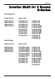
SiBE12-816_D Inverter Multi for 2 Rooms G-Series zCooling Only Outdoor Unit Indoor Unit 2MKS40GV1B 2MKS40G2V1B 2MKS50GV1B 2MKS50G2V1B FTXS20G2V1B FTXS25G2V1B FTXS35G2V1B FTXS42G2V1B FTXS50G2V1B FTXS20J2V1B FTXS25J2V1B FTXS35J2V1B FTXS42J2V1B FTXS50J2V1B FVXS25FV1B FVXS35FV1B FVXS50FV1B FLKS25BAVMB FLKS35BAVMB FLKS50BAVMB FDKS25EAVMB FDKS35EAVMB FDKS50CVMB FFQ25B8V1B FFQ35B8V1B FFQ50B8V1B zHeat Pump Outdoor Unit Indoor Unit 2MXS40GV1B 2MXS40G2V1B 2MXS50GV1B 2MXS50G2V1B FTXG25EV1BW(S) FTXG35EV1BW(S)
SiBE12-816_D 1. Introduction ............................................................................................ vi 1.1 Safety Cautions ....................................................................................... vi 1.2 Used Icons ...............................................................................................x Part 1 List of Functions ................................................................ 1 1. Functions..........................................................
SiBE12-816_D 2.3 Freeze Prevention Control .....................................................................77 2.4 Hot Start Control (In Heating Operation Only)........................................78 3. Function of Thermistor ..........................................................................79 4. Control Specification .............................................................................81 4.1 4.2 4.3 4.4 4.5 4.6 4.7 4.8 4.9 4.10 4.11 4.12 Mode Hierarchy ............................
SiBE12-816_D 6. Troubleshooting for SA Indoor Unit - FFQ Series ...............................223 6.1 6.2 6.3 6.4 6.5 6.6 6.7 Indoor Unit PCB Abnormality ...............................................................223 Drain Water Level System Abnormality................................................224 Fan Motor or Related Abnormality .......................................................226 Drain System Abnormality....................................................................
SiBE12-816_D 1.2 1.3 1.4 1.5 1.6 1.7 1.8 Removal of Electrical Box ....................................................................275 Removal of PCB...................................................................................280 Removal of Sound Blankets .................................................................285 Removal of Outdoor Fan / Fan Motor...................................................287 Removal of Thermistors ...............................................................
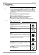
SiBE12-816_D Introduction 1. Introduction 1.1 Safety Cautions Cautions and Warnings Be sure to read the following safety cautions before conducting repair work. The caution items are classified into “ Warning” and “ Caution”. The “ Warning” items are especially important since they can lead to death or serious injury if they are not followed closely. The “ Caution” items can also lead to serious accidents under some conditions if they are not followed.
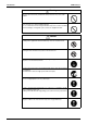
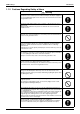
Introduction SiBE12-816_D Warning Be sure to wear a safety helmet, gloves, and a safety belt when working at a high place (more than 2 m). Insufficient safety measures may cause a fall accident. In case of R-410A refrigerant models, be sure to use pipes, flare nuts and tools for the exclusive use of the R-410A refrigerant. The use of materials for R-22 refrigerant models may cause a serious accident such as a damage of refrigerant cycle as well as an equipment failure.
SiBE12-816_D Introduction 1.1.2 Cautions Regarding Safety of Users Warning Be sure to use parts listed in the service parts list of the applicable model and appropriate tools to conduct repair work. Never attempt to modify the equipment. The use of inappropriate parts or tools may cause an electrical shock, excessive heat generation or fire. If the power cable and lead wires have scratches or deteriorated, be sure to replace them.
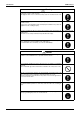
Introduction SiBE12-816_D Warning Check to make sure that the power cable plug is not dirty or loose, then insert the plug into a power outlet securely. If the plug has dust or loose connection, it may cause an electrical shock or fire. Be sure to install the product correctly by using the provided standard For unitary type only installation frame. Incorrect use of the installation frame and improper installation may cause the equipment to fall, resulting in injury.
SiBE12-816_D Introduction Caution Be sure to measure the insulation resistance after the repair, and make sure that the resistance is 1 MΩ or higher. Faulty insulation may cause an electrical shock. Be sure to check the drainage of the indoor unit after the repair. Faulty drainage may cause the water to enter the room and wet the furniture and floor. Do not tilt the unit when removing it. The water inside the unit may spill and wet the furniture and floor.
SiBE12-816_D Part 1 List of Functions 1. Functions.................................................................................................2 1.1 Cooling Only.............................................................................................2 1.2 Heat Pump ...............................................................................................
SiBE12-816_D Functions 1. Functions Compressor Comfortable Airflow Comfort Control Operation Lifestyle Convenience Inverter (with Inverter Power Control) { { Operation Limit for Cooling (°CDB) — — Operation Limit for Heating (°CWB) — — PAM Control — — FVXS25/35/50FV1B Basic Function Functions FTXS20/25/35/42/50G2V1B FTXS20/25/35/42/50J2V1B Category FVXS25/35/50FV1B Cooling Only FTXS20/25/35/42/50G2V1B FTXS20/25/35/42/50J2V1B 1.
Compressor Comfortable Airflow Comfort Control Operation Lifestyle Convenience Inverter (with Inverter Power Control) { { Operation Limit for Cooling (°CDB) — — Operation Limit for Heating (°CWB) — — PAM Control — — FDKS25/35EAVMB FDKS50CVMB Basic Function Functions FLKS25/35/50BAVMB Category FDKS25/35EAVMB FDKS50CVMB SiBE12-816_D FLKS25/35/50BAVMB Functions Air-Purifying Filter { — Photocatalytic Deodorizing Filter { — Air-Purifying Filter with Photocatalytic Deodorizing Fun
Compressor Comfortable Airflow Comfort Control Operation Lifestyle Convenience { Operation Limit for Cooling (°CDB) — 10 ~46 Operation Limit for Heating (°CWB) — — PAM Control — { 2MKS40/50GV1B 2MKS40/50G2V1B { Inverter (with Inverter Power Control) FFQ25/35/50B8V1B Basic Function Functions 2MKS40/50GV1B 2MKS40/50G2V1B Category Functions FFQ25/35/50B8V1B SiBE12-816_D Air-Purifying Filter — — Photocatalytic Deodorizing Filter — — Air-Purifying Filter with Photocatalytic Deodor
Functions Comfortable Airflow Comfort Control Operation Lifestyle Convenience Air-Purifying Filter — — Photocatalytic Deodorizing Filter — — — Air-Purifying Filter with Photocatalytic Deodorizing Function — — Inverter (with Inverter Power Control) { { Operation Limit for Cooling (°CDB) — — Operation Limit for Heating (°CWB) Compressor CTXG50EV1BW(S) Basic Function Functions CTXG50EV1BW(S) Category FTXG25/35EV1BW(S) Heat Pump FTXG25/35EV1BW(S) 1.
Basic Function Compressor Comfortable Airflow Comfort Control Operation Lifestyle Convenience Inverter (with Inverter Power Control) { { Operation Limit for Cooling (°CDB) — — Operation Limit for Heating (°CWB) — Health & Clean Functions CTXG50JV1BW(S) Category FTXG25/35JV1BW(S) Functions CTXG50JV1BW(S) Category Functions FTXG25/35JV1BW(S) SiBE12-816_D Air-Purifying Filter — — Photocatalytic Deodorizing Filter — — — Air-Purifying Filter with Photocatalytic Deodorizing Functio
Basic Function Compressor Comfortable Airflow Comfort Control Operation Lifestyle Convenience Inverter (with Inverter Power Control) { { Operation Limit for Cooling (°CDB) — — Operation Limit for Heating (°CWB) — Category Health & Clean Functions FVXS25/35/50FV1B Functions FTXS20/25/35/42/50G2V1B Category FVXS25/35/50FV1B SiBE12-816_D FTXS20/25/35/42/50G2V1B Functions Air-Purifying Filter — — Photocatalytic Deodorizing Filter — — — Air-Purifying Filter with Photocatalytic Deo
Compressor Comfortable Airflow Comfort Control Operation Lifestyle Convenience { { Operation Limit for Cooling (°CDB) — — FDXS25/35EAVMB FDXS50CVMB Inverter (with Inverter Power Control) FLXS25/35/50BAVMB Basic Function Functions FDXS25/35EAVMB FDXS50CVMB Category Functions FLXS25/35/50BAVMB SiBE12-816_D Air-Purifying Filter { — Photocatalytic Deodorizing Filter { — Air-Purifying Filter with Photocatalytic Deodorizing Function — — — — Category Health & Clean Functions Opera
Compressor Comfortable Airflow Comfort Control Operation Lifestyle Convenience { { Operation Limit for Cooling (°CDB) — 10 ~46 Operation Limit for Heating (°CWB) — –15 ~15.
SiBE12-816_D Part 2 Specifications 1. Specifications ........................................................................................11 1.1 1.2 1.3 1.4 Specifications Cooling Only - Indoor Unit ......................................................................11 Cooling Only - Outdoor Unit ...................................................................18 Heat Pump - Indoor Unit.........................................................................20 Heat Pump - Outdoor Unit.............
Specifications SiBE12-816_D 1. Specifications 1.
SiBE12-816_D Specifications 50 Hz, 220 - 230 - 240 V Model Rated Capacity Front Panel Color H M Airflow Rates L SL Type Fan Motor Output Speed Air Direction Control Air Filter Running Current (Rated) Power Consumption (Rated) Power Factor (Rated) Temperature Control Dimensions (H × W × D) Packaged Dimensions (H × W × D) Weight (Mass) Gross Weight (Gross Mass) Operation H / M / L / SL Sound Sound Power Heat Insulation Liquid Piping Connection Gas Drain Drawing No.
Specifications SiBE12-816_D 50 Hz, 220 - 230 - 240 V Model Rated Capacity Front Panel Color H M Airflow Rates L SL Type Fan Motor Output Speed Air Direction Control Air Filter Running Current (Rated) Power Consumption (Rated) Power Factor (Rated) Temperature Control Dimensions (H × W × D) Packaged Dimensions (H × W × D) Weight (Mass) Gross Weight (Gross Mass) Operation H / M / L / SL Sound Sound Power Heat Insulation Liquid Gas Piping Connections Indoor Unit Drain Outdoor Unit Drawing No.
SiBE12-816_D Specifications Floor Standing Type 50 Hz, 220 - 230 - 240 V Model Rated Capacity Front Panel Color H M Airflow Rates L SL Type Fan Motor Output Speed Air Direction Control Air Filter Running Current (Rated) Power Consumption (Rated) Power Factor (Rated) Temperature Control Dimensions (H × W × D) Packaged Dimensions (H × W × D) Weight (Mass) Gross Weight (Gross Mass) Operation H / M / L / SL Sound Sound Power Heat Insulation Liquid Piping Connection Gas Drain Drawing No.
Specifications SiBE12-816_D Floor / Ceiling Suspended Dual Type 50 Hz, 220 - 230 - 240 V Model Rated Capacity Front Panel Color H M Airflow Rates L SL Type Fan Motor Output Speed Air Direction Control Air Filter Running Current (Rated) Power Consumption (Rated) Power Factor (Rated) Temperature Control Dimensions (H × W × D) Packaged Dimensions (H × W × D) Weight (Mass) Gross Weight (Gross Mass) Operation H / M / L / SL Sound Sound Power Heat Insulation Liquid Piping Connection Gas Drain Drawing No.
SiBE12-816_D Specifications Duct Connected Type 50 Hz, 230 V Model Rated Capacity Front Panel Color H M Airflow Rates L SL Type Fan Motor Output Speed Air Filter Running Current (Rated) Power Consumption (Rated) Power Factor (Rated) Temperature Control Dimensions (H × W × D) Packaged Dimensions (H × W × D) Weight (Mass) Gross Weight (Gross Mass) Operation H / M / L / SL Sound Sound Power External Static Pressure Heat Insulation Liquid Piping Connection Gas Drain Drawing No.
Specifications SiBE12-816_D Ceiling Mounted Cassette Type 50 Hz, 230 V Model Rated Capacity Color Decoration Panel Dimensions (H × W × D) H M Airflow Rates L SL Type Fan Motor Output Speed Air Direction Control Air Filter Running Current (Rated) Power Consumption (Rated) Power Factor (Rated) Temperature Control Dimensions (H × W × D) ★1 Packaged Dimensions (H × W × D) Weight (Mass) Gross Weight (Gross Mass) Operation H/L Sound Sound Power Heat Insulation Liquid Piping Connection Gas Drain Drawing No.
SiBE12-816_D 1.2 Specifications Cooling Only - Outdoor Unit 50 Hz, 220 - 240 V Model Casing Color Type Model Motor Output Model Refrigerant Oil Charge Type Refrigerant Charge HH H L Airflow Rate HH H L Type Fan Motor Output Starting Current Dimension (H × W × D) Packaged Dimension (H × W × D) Weight (Mass) Gross Weight (Gross Mass) Operation Sound Sound Power Liquid Piping Gas Connection Drain Heat Insulation No. of Wiring Connection Compressor Max.
Specifications SiBE12-816_D 50 Hz, 220 - 240 V Model Casing Color Type Model Motor Output Model Refrigerant Oil Charge Type Refrigerant Charge HH H L Airflow Rates HH H L Type Fan Motor Output Starting Current Dimensions (H × W × D) Packaged Dimensions (H × W × D) Weight (Mass) Gross Weight (Gross Mass) Operation Sound Sound Power Liquid Piping Gas Connection Drain Heat Insulation No. of Wiring Connection Compressor Max. Interunit Piping Length Min.
SiBE12-816_D 1.
Specifications SiBE12-816_D 50 Hz, 220 - 230 - 240 V CTXG50EV1BW Model Rated Capacity Front Panel Color H M Airflow Rates L SL Type Fan Motor Output Speed Air Direction Control Air Filter Running Current (Rated) Power Consumption (Rated) Power Factor (Rated) Temperature Control Dimensions (H × W × D) Packaged Dimensions (H × W × D) Weight (Mass) Gross Weight (Gross Mass) Operation H / M / L / SL Sound Sound Power Heat Insulation Liquid Piping Connection Gas Drain Drawing No. Cooling Cooling 5.
SiBE12-816_D Specifications 50 Hz, 220 - 230 - 240 V FTXG35JV1BW Model Rated Capacity Front Panel Color H M Airflow Rates L SL Type Fan Motor Output Speed Air Direction Control Air Filter Running Current (Rated) Power Consumption (Rated) Power Factor (Rated) Temperature Control Dimensions (H × W × D) Packaged Dimensions (H × W × D) Weight (Mass) Gross Weight (Gross Mass) Operation H / M / L / SL Sound Sound Power Heat Insulation Liquid Piping Connection Gas Drain Drawing No.
Specifications SiBE12-816_D 50 Hz, 220 - 230 - 240 V FTXS20G2V1B Model Rated Capacity Front Panel Color H M Airflow Rates L SL Type Fan Motor Output Speed Air Direction Control Air Filter Running Current (Rated) Power Consumption (Rated) Power Factor (Rated) Temperature Control Dimensions (H × W × D) Packaged Dimensions (H × W × D) Weight (Mass) Gross Weight (Gross Mass) Operation H / M / L / SL Sound Sound Power Heat Insulation Liquid Piping Connection Gas Drain Drawing No.
SiBE12-816_D Specifications 50 Hz, 220 - 230 - 240 V FTXS50G2V1B Model Rated Capacity Front Panel Color H M Airflow Rates L SL Type Fan Motor Output Speed Air Direction Control Air Filter Running Current (Rated) Power Consumption (Rated) Power Factor (Rated) Temperature Control Dimensions (H × W × D) Packaged Dimensions (H × W × D) Weight (Mass) Gross Weight (Gross Mass) Operation H / M / L / SL Sound Sound Power Heat Insulation Liquid Piping Connection Gas Drain Drawing No. Cooling Heating 5.
Specifications SiBE12-816_D Floor Standing Type 50 Hz, 220 - 230 - 240 V FVXS25FV1B Model Rated Capacity Front Panel Color H M Airflow Rates L SL Type Fan Motor Output Speed Air Direction Control Air Filter Running Current (Rated) Power Consumption (Rated) Power Factor (Rated) Temperature Control Dimensions (H × W × D) Packaged Dimensions (H × W × D) Weight (Mass) Gross Weight (Gross Mass) Operation H / M / L / SL Sound Sound Power Heat Insulation Liquid Piping Connection Gas Drain Drawing No.
SiBE12-816_D Specifications Floor / Ceiling Suspended Dual Type 50 Hz, 220 - 230 - 240 V FLXS25BAVMB Model Rated Capacity Front Panel Color H M Airflow Rates L SL Type Fan Motor Output Speed Air Direction Control Air Filter Running Current (Rated) Power Consumption (Rated) Power Factor (Rated) Temperature Control Dimensions (H × W × D) Packaged Dimensions (H × W × D) Weight (Mass) Gross Weight (Gross Mass) Operation H / M / L / SL Sound Sound Power Heat Insulation Liquid Piping Connection Gas Drain Drawi
Specifications SiBE12-816_D Duct Connected Type 50 Hz, 230 V FDXS25EAVMB Model Rated Capacity Front Panel Color H M Airflow Rates L SL Type Fan Motor Output Speed Air Filter Running Current (Rated) Power Consumption (Rated) Power Factor (Rated) Temperature Control Dimensions (H × W × D) Packaged Dimensions (H × W × D) Weight (Mass) Gross Weight (Gross Mass) Operation H / M / L / SL Sound Sound Power External Static Pressure Heat Insulation Liquid Piping Connection Gas Drain Drawing No.
SiBE12-816_D Specifications Ceiling Mounted Cassette Type 50 Hz, 230 V FFQ25B8V1B Model Cooling Rated Capacity Color Decoration Panel Dimensions (H × W × D) H M Airflow Rates L SL Type Fan Motor Output Speed Air Direction Control Air Filter Running Current (Rated) Power Consumption (Rated) Power Factor (Rated) Temperature Control Dimensions (H × W × D) ★1 Packaged Dimensions (H × W × D) Weight (Mass) Gross Weight (Gross Mass) Operation H/L Sound Sound Power Heat Insulation Liquid Piping Connection Gas
Specifications 1.4 SiBE12-816_D Heat Pump - Outdoor Unit 50 Hz, 220 - 240 V 2MXS40GV1B Model Cooling Casing Color Type Model Motor Output Model Refrigerant Oil Charge Type Refrigerant Charge HH H L Airflow Rate HH H L Type Fan Motor Output Starting Current Dimension (H × W × D) Packaged Dimension (H × W × D) Weight (Mass) Gross Weight (Gross Mass) Operation Sound Sound Power Liquid Piping Gas Connection Drain Heat Insulation No. of Wiring Connection Compressor Max.
SiBE12-816_D Specifications 50 Hz, 220 - 240 V 2MXS50GV1B Model Cooling Casing Color Type Model Motor Output Model Refrigerant Oil Charge Type Refrigerant Charge HH H L Airflow Rates HH H L Type Fan Motor Output Starting Current Dimensions (H × W × D) Packaged Dimensions (H × W × D) Weight (Mass) Gross Weight (Gross Mass) Operation Sound Sound Power Liquid Piping Gas Connection Drain Heat Insulation No. of Wiring Connection Compressor Max. Interunit Piping Length Min.
SiBE12-816_D Part 3 Printed Circuit Board Connector Wiring Diagram 1. Indoor Unit.............................................................................................32 1.1 1.2 1.3 1.4 1.5 Wall Mounted Type ................................................................................32 Floor Standing Type ...............................................................................40 Floor / Ceiling Suspended Dual Type.....................................................
SiBE12-816_D Indoor Unit 1. Indoor Unit 1.1 Wall Mounted Type 1.1.
Indoor Unit PCB Detail SiBE12-816_D PCB (1): Control PCB S51 S1 S49 S41 JB JA JC LED A FG S21 H2 H1B S32 FU V1 S46 H3 S36 2P165085-1 PCB (2): Signal Receiver PCB S47 RTH1 SW1 LED4 LED2 LED3 2P165085-1 PCB (3): INTELLIGENT EYE Sensor PCB S36 3P043610-2 33 Printed Circuit Board Connector Wiring Diagram
SiBE12-816_D Indoor Unit 1.1.
Indoor Unit PCB Detail SiBE12-816_D PCB (1): Control PCB S42 S41 JB JC S46 S32 S25 LED A S200 S21 H3 H2 FG V1 F1U H1 2P254830-1 35 Printed Circuit Board Connector Wiring Diagram
SiBE12-816_D Indoor Unit PCB (2): Signal Receiver / Display PCB S52 S51 H2P H1P S1W JA 3P254832-1 PCB (3): INTELLIGENT EYE Sensor PCB S36 3P255914-1 Printed Circuit Board Connector Wiring Diagram 36
Indoor Unit SiBE12-816_D 1.1.
SiBE12-816_D PCB Detail Indoor Unit PCB (1): Control PCB V1 H1 FU1 H2 FG H3 LED A S32 S1 S21 JB JA JC S41 S47 S46 S25 2P206687-1 Printed Circuit Board Connector Wiring Diagram 38
Indoor Unit SiBE12-816_D PCB (2): Signal Receiver PCB S48 3P210728-1 PCB (3): Display PCB RTH1 SW1 LED3 LED2 S49 LED1 3P210728-1 PCB (4): INTELLIGENT EYE Sensor PCB S26 3EB86013-1 39 Printed Circuit Board Connector Wiring Diagram
SiBE12-816_D 1.2 Indoor Unit Floor Standing Type 1.2.
Indoor Unit PCB Detail SiBE12-816_D PCB (1): Sensor PCB RTH2 S49 3P191450-1 PCB (2): Control PCB E1 H1 JB V2 JA JC V1 S32 H2 S48 FU1 S46 H3 S1 LED A S21 S41 S42 S26 2P191446-1 PCB (3): Service PCB PCB (4): Display PCB SW4 S27 LED1 LED2 3P191448-1 41 SW1 S47 3P191447-1 SW2-4 ★ LED3 does not function.
SiBE12-816_D 1.3 Indoor Unit Floor / Ceiling Suspended Dual Type 1.3.
Indoor Unit PCB Detail SiBE12-816_D PCB (1): Control PCB S21 LED A SW2 S7 S26 S6 S32 S24 JC JB JA S37 2P084352-3 PCB (2): Power Supply PCB H4 S36 H5 H6 H1 FU1 H2 V1 H3 2P084361-1 PCB (3): Display PCB LED2 LED1 SW1 S25 SW1 2P084377-5 EX511 REV 12 PbF S27 RTH I PHOTO 2P084377- S31 (RTH) 43 S27 C1 C2 3 LED3 PCB (4): Signal Receiver PCB WLU C3 2P084377-5 Printed Circuit Board Connector Wiring Diagram
SiBE12-816_D 1.4 Indoor Unit Duct Connected Type 1.4.
Indoor Unit PCB Detail SiBE12-816_D PCB (1): Control PCB FU1 S1 H2 H1 H3 V1 GND S7 S21 JA LED A JB JC S32 S26 2P131149-1 PCB (2): Display PCB S1 LED3 LED2 RTH1 LED1 SW1 2P084375-1 45 Printed Circuit Board Connector Wiring Diagram
SiBE12-816_D 1.5 Indoor Unit Ceiling Mounted Cassette Type 1.5.
Indoor Unit PCB Detail SiBE12-816_D [A1P]: Control PCB X20A X25A X27A X11A X10A X33A X18A X19A X61A X60A X36A X40A HAP X17A X15A X24A 47 X35A X5A 2P095006-8 Printed Circuit Board Connector Wiring Diagram
SiBE12-816_D Remote Controller 2. Remote Controller 2.1 Wired Remote Controller 2.1.1 BRC1D528 Connectors and Other Parts 1) P1, P2 2) R1T 3) SS1 Terminal for indoor unit Room temperature thermistor MAIN / SUB setting switch ∗ Refer to page 310 for detail.
Remote Controller 2.2 SiBE12-816_D Wireless Remote Controller 2.2.1 BRC7E530W/531W Connectors and Other Parts [A3P]: Signal Receiver PCB 1) X1A 2) X2A 3) SS1 SS2 Connector for display PCB Connector for control PCB MAIN / SUB setting switch Address setting switch ∗ Refer to page 311 for detail.
SiBE12-816_D Outdoor Unit 3. Outdoor Unit 3.
Outdoor Unit PCB Detail SiBE12-816_D 40 class HR1 HL1 E HN2 HR2 FU3 FU1 FU2 V4 V3 V1 S-A S-B LED A S80 S21 S20 S91 S90 S92 S40 S45 J3 J4 J5 S70 U, V, W 2P190760-2 50 class HL1 E2 HN1 FU3 FU1 FU2 HR2 HR1 V4 V3 V1 S-A S-B LED A S80 S21 S20 S91 S92 S90 S40 S70 S45 J3 J4 J5 U, V, W 2P197402-1 51 Printed Circuit Board Connector Wiring Diagram
SiBE12-816_D Part 4 Function and Control 1. Function of Indoor Unit (RA Models).....................................................53 1.1 1.2 1.3 1.4 1.5 1.6 1.7 1.8 1.9 1.10 1.11 1.12 1.13 1.14 1.15 Temperature Control ..............................................................................53 Frequency Principle................................................................................53 Operation Starting Control......................................................................
Function of Indoor Unit (RA Models) SiBE12-816_D 1. Function of Indoor Unit (RA Models) 1.1 Temperature Control Definitions of Temperatures The definitions of temperatures are classified as following.
SiBE12-816_D Drawing of Inverter Function of Indoor Unit (RA Models) The following drawing shows a schematic view of the inverter principle: Refrigerant circulation rate (high) AC power Amount of heat exchanged air (small) DC power high speed Amount of heat exchanged air (large) high f low f low speed 50 Hz freq= constant 60 Hz freq=variable Amount of heat exchanged air (large) Amount of heat exchanged air (small) capacity= variable Refrigerant circulation rate (low) Inverter Features (R2812)
Function of Indoor Unit (RA Models) 1.3 SiBE12-816_D Operation Starting Control Wall Mounted Type: FTXG, CTXG Series The system carries out the following control at the beginning to conduct every functional parts properly. 1. Opening the front panel fully 2. Output of the ∆D signal after the front panel starts moving 3. Opening the flap fully after the front panel opens fully 4.
SiBE12-816_D 1.4 Function of Indoor Unit (RA Models) Airflow Direction Control Power-Airflow Dual Flaps The large flaps send a large volume of air downwards to the floor. The flap provides an optimum control in cooling, dry, and heating mode. Cooling / Dry Mode During cooling or dry mode, the flap retracts into the indoor unit. Then, cool air can be blown far and pervaded all over the room.
Function of Indoor Unit (RA Models) SiBE12-816_D Floor / Ceiling Suspended Dual Type Vertical Swing (up and down) Cooling / Dry / Fan Heating 65˚ 20˚ 40˚ Ceiling 95 ˚ (R2964) (R2963) 95 ˚ 40˚ 20˚ Floor (R2966) (R2967) 3-D Airflow ˚ 65 Wall Mounted Type: FTXS Series Alternative repetition of vertical and horizontal swing motions enables uniform air-conditioning of the entire room. This function is effective for starting the air conditioner.
SiBE12-816_D 1.5 Function of Indoor Unit (RA Models) Fan Speed Control for Indoor Units Outline Phase control and fan speed control contains 9 steps: LLL, LL, SL, L, ML, M, MH, H, and HH. The airflow rate can be automatically controlled depending on the difference between the room thermistor temperature and the target temperature. This is done through phase control and Hall IC control. For more information about Hall IC, refer to the troubleshooting for fan motor on page 218, 219.
Function of Indoor Unit (RA Models) COMFORT AIRFLOW Operation 1.6 SiBE12-816_D Wall Mounted Type The fan speed is controlled automatically within the following steps. Cooling: L tap – MH tap (same as AUTOMATIC) Heating: ML tap – M tap ~ MH tap (depending on the model) The latest command has the priority between POWERFUL and COMFORT AIRFLOW. Program Dry Operation Outline Program dry operation removes humidity while preventing the room temperature from lowering.
SiBE12-816_D 1.7 Function of Indoor Unit (RA Models) Automatic Operation Outline Detail Automatic Cooling / Heating Function When the AUTO mode is selected with the remote controller, the microcomputer automatically determines the operation mode as cooling or heating according to the room temperature and the set temperature at start-up, and automatically operates in that mode. The unit automatically switches the operation mode to maintain the room temperature at the set temperature.
Function of Indoor Unit (RA Models) 1.8 SiBE12-816_D Thermostat Control Thermostat control is based on the difference between the room thermistor temperature and the target temperature. Thermostat OFF Condition The temperature difference is in the zone A. Thermostat ON Condition The temperature difference returns to the zone C after being in the zone A. The system resumes from defrost control in any zones except A. The operation turns on in any zones except A.
SiBE12-816_D Function of Indoor Unit (RA Models) Heating Wall Mounted Type: FTXG-J, CTXG-J Series Room thermistor temperature – target temperature OFF A 2.0˚C B 1.5˚C C 0.5˚C ON (R11894) Wall Mounted Type: FTXG-E, CTXG-E, FTXS Series Floor Standing Type Room thermistor temperature – target temperature OFF A 1.5˚C B 1.0˚C C 0˚C ON (R12320) Floor / Ceiling Suspended Dual Type Duct Connected Type Room thermistor temperature – target temperature OFF A 1.5˚C B 1.0˚C C 0.
Function of Indoor Unit (RA Models) 1.9 SiBE12-816_D NIGHT SET Mode Outline When the OFF timer is set, the NIGHT SET Mode is automatically activated. The NIGHT SET Mode keeps the airflow rate setting. Detail The NIGHT SET Mode continues operation at the target temperature for the first one hour, then automatically raises the target temperature slightly in the case of cooling, or lowers it slightly in the case of heating.
SiBE12-816_D Function of Indoor Unit (RA Models) 1.10 ECONO Operation FTXG-J, CTXG-J, FTXS, FVXS Series The "ECONO operation" reduces the maximum operating current and power consumption during start-up etc.. This operation is particularly convenient for energy-saving-oriented users. It is also a major bonus for those whose breaker capacities do not allow the use of multiple electrical devices and air conditioners. It is easily activated from the wireless remote controller by pushing the ECONO button.
Function of Indoor Unit (RA Models) SiBE12-816_D 1.11 HOME LEAVE Operation Outline FLK(X)S, FDK(X)S Series HOME LEAVE operation is a function that allows you to record your favorite set temperature and airflow rate. You can start your favorite operation mode simply by pressing the [HOME LEAVE] button on the remote controller. Detail 1.
SiBE12-816_D Function of Indoor Unit (RA Models) 1.12 2-Area INTELLIGENT EYE Operation Outline Wall Mounted Type: FTXS Series The following functions can be performed by a motion sensor (INTELLIGENT EYE). 1. Reduction of the capacity when there is nobody in the room in order to save electricity (energy saving operation) 2. Dividing the room into plural areas and detecting existence of humans in each area.
Function of Indoor Unit (RA Models) SiBE12-816_D 2. Motions (for example: in cooling) within 20 minutes Human detection signal ON OFF (From area A or B) 20 min. 20 min. RESET.
SiBE12-816_D Function of Indoor Unit (RA Models) 1.13 INTELLIGENT EYE Operation Outline Wall Mounted Type: FTXG, CTXG Series This is the function that detects existence of humans in the room by a human motion sensor (INTELLIGENT EYE) and reduces the capacity when there is nobody in the room in order to save electricity. Detail 1. Detection method by INTELLIGENT EYE sampling (20 msec.) Sensor output If the sensor detects the outputs 10 times/sec. or more, it judges humans exist. 1 sec.
Function of Indoor Unit (RA Models) SiBE12-816_D 1.14 Inverter POWERFUL Operation Outline In order to exploit the cooling and heating capacity to full extent, operate the air conditioner by increasing the indoor fan rotating speed and the compressor frequency. Detail When POWERFUL button is pressed, the fan speed and target temperature are converted to the following states for 20 minutes.
SiBE12-816_D Brightness Setting Function of Indoor Unit (RA Models) The brightness of the multi-colored indicator lamp can be adjusted L (low), H (high), or OFF. 1. Press the center of the Temp button and the Mode button at the same time. (R11669) “5C” is displayed on the LCD. (R11911) 2. Select “L” (light) with the Temp ▲ or ▼ button. (R11912) 3. Press the Mode button to enter the brightness setting mode. 4. Press the Temp ▲ or ▼ button to adjust the brightness of the multi-colored indicator lamp.
Function of Indoor Unit (RA Models) SiBE12-816_D 1.15 Other Functions 1.15.1 Hot-Start Function In order to prevent the cold air blast that normally comes when heating operation is started, the temperature of the indoor heat exchanger is detected, and either the airflow is stopped or is made very weak thereby carrying out comfortable heating of the room. *The cold air blast is also prevented using a similar control when the defrosting operation is started or when the thermostat is turned ON. 1.15.
SiBE12-816_D Function of Indoor Unit (RA Models) 1.15.7 Auto-restart Function Even if a power failure (including one for just a moment) occurs during the operation, the operation restarts automatically when the power is restored in the same condition as before the power failure. Note: It takes 3 minutes to restart the operation because the 3-minute standby function is activated. 1.15.8 WEEKLY TIMER Operation Up to 4 timer settings can be saved for each day of the week (up to 28 settings in total).
Function of Indoor Unit (SA Models) SiBE12-816_D 2. Function of Indoor Unit (SA Models) 2.1 Drain Pump Control 2.1.1 When the Float Switch is Tripped While the Cooling Thermostat is ON: The remote controller displays "A3" and the indoor unit stops. ON Thermostat (running) OFF OFF Float switch ON ON Drain pump OFF 5 min. 5 min. 5 sec. *1) Normal operation *2) Malfunction residual (R12933) ∗1.
SiBE12-816_D Function of Indoor Unit (SA Models) 2.1.3 When the Float Switch is Tripped During Heating Operation: Thermostat (running) ON The remote controller displays "A3" and the indoor unit stops. OFF ON Humidifier OFF Float switch Reset ON OFF Drain pump ON OFF 5 min. 5 sec. 5 min. (R12935) During heating operation, if the float switch is not reset even after the 5 minutes operation, 5 seconds stop, 5 minutes operation cycle ends, operation continues until the switch is reset. 2.1.
Function of Indoor Unit (SA Models) 2.2 SiBE12-816_D Thermostat Sensor in Remote Controller Temperature is controlled by both the thermostat sensor in remote controller and air suction thermostat in the indoor unit. (This is however limited to when the field setting for the thermostat sensor in remote controller is set to “Use”.
SiBE12-816_D Heating Function of Indoor Unit (SA Models) When heating, the hot air rises to the top of the room, resulting in the temperature being lower near the floor where the occupants are. When controlling by body thermostat sensor only, the indoor unit may therefore be turned off by the thermostat before the lower part of the room reaches the set temperature.
Function of Indoor Unit (SA Models) 2.3 SiBE12-816_D Freeze Prevention Control When the temperature detected by liquid pipe thermistor (R2T) of the indoor heat exchanger drops too low, the unit enters freeze prevention control in accordance with the following conditions, and is also set in accordance with the conditions given below. Conditions for starting: Temperature is –1°C or less for total of 40 min., or temperature is –5°C or less for total of 10 min.
SiBE12-816_D 2.4 Function of Indoor Unit (SA Models) Hot Start Control (In Heating Operation Only) Outline At startup with thermostat ON or after the completion of defrosting in heating operation, the indoor unit fan is controlled to prevent cold air from blasting out and ensure startup capacity.
Function of Thermistor SiBE12-816_D 3. Function of Thermistor Expansion valve E EVA EVB A Four way valve D B C Compressor (R7042) A Outdoor Heat Exchanger Thermistor 1. The outdoor heat exchanger thermistor is used for controlling target discharge pipe temperature. The system sets the target discharge pipe temperature according to the outdoor and indoor heat exchanger temperature, and controls the electronic expansion valve opening so that the target discharge pipe temperature can be obtained. 2.
SiBE12-816_D Function of Thermistor D Indoor Heat Exchanger Thermistor 1. The indoor heat exchanger thermistor is used for controlling target discharge pipe temperature. The system sets the target discharge pipe temperature according to the outdoor and indoor heat exchanger temperature, and controls the electronic expansion valve opening so that the target discharge pipe temperature can be obtained. 2. In cooling operation, the indoor heat exchanger thermistor is used for freeze-up protection control.
Control Specification SiBE12-816_D 4. Control Specification 4.1 Mode Hierarchy Outline There are two modes; the one is the normal operation mode and the other is the forced operation mode for installation and providing service. Detail Cooling only model There are following models; stop and cooling (includes drying).
SiBE12-816_D Control Specification Determine Operation Mode The system judges the operation mode command which is set by each room in accordance with the procedure, and determines the operation mode of the system. The following procedure is taken when the modes conflict with each other. *1. The system follows the mode which is set first. (First-push, first-set) *2. For the rooms where the different mode is set, standby mode is activated. (The operation lamp blinks.
Control Specification 4.2 Outline SiBE12-816_D Frequency Control Frequency that corresponds to each room’s capacity is determined according to the difference between the target temperature and the temperature of each room. The function is explained as follows. 1. How to determine frequency 2. Frequency command from an indoor unit (Difference between a room thermistor temperature and the target temperature) 3. Frequency command from an indoor unit (The ranked capacity of the operating room) 4.
SiBE12-816_D Control Specification For Heat Pump Model 1. Determine command frequency Command frequency is determined in the following order of priority. 1. Limiting defrost control time 2. Forced cooling / heating 3. Indoor frequency command 2.
Control Specification SiBE12-816_D PI Control (Determine Frequency Up / Down by ∆D Signal) 1. P control A total of the ∆D value is calculated in each sampling time (20 seconds), and the frequency is adjusted according to its difference from the frequency previously calculated. 2. I control If the operating frequency is not change more than a certain fixed time, the frequency is adjusted according to the Σ∆D value. When the Σ∆D value is small...lower the frequency. When the Σ∆D value is large...
SiBE12-816_D 4.3 Control Specification Controls at Mode Changing / Start-up 4.3.1 Preheating Operation Outline The inverter operation in open phase starts with the conditions of the preheating command from the indoor, the outdoor temperature, and discharge pipe temperature. Detail ON Condition When outdoor temperature is below 10.5°C and discharge pipe temperature is below 10.5°C, the inverter operation in open phase starts.
Control Specification SiBE12-816_D 4.3.5 Compressor Protection Function When turning the compressor from OFF to ON, the upper limit of frequency is set as follows. (The function is not used when defrosting.) (Hz) Frequency C B A D A B C D E F 4.4 Outline E (sec.) Time F (R13528) 40 class 62 50 class 55 Unit 72 70 Hz 90 85 140 150 180 180 300 300 seconds Discharge Pipe Temperature Control The discharge pipe temperature is used as the internal temperature of the compressor.
SiBE12-816_D 4.5 Control Specification Input Current Control Outline An input current is detected by the CT during the compressor is running, and the frequency upper limit is set from the input current. In case of heat pump model, this control, which is the upper limit control of the frequency, takes priority to the lower limit control of four way valve operation compensation.
Control Specification 4.7 SiBE12-816_D Heating Peak-cut Control Outline During heating operation, the indoor heat exchanger temperature determines the frequency upper limit to prevent abnormal high pressure. Detail The operating frequency is judged with the indoor heat exchanger temperature 2 minutes after the operation starts and A seconds after the number of operation room is changed. The maximum value of the indoor heat exchanger temperature controls the following (excluding stopped rooms).
SiBE12-816_D 4.9 Control Specification Liquid Compression Protection Function Outline In order to obtain the dependability of the compressor, the compressor is stopped according to the outdoor temperature and temperature of the outdoor heat exchanger. Detail Operation stops depending on the outdoor temperature Compressor turns off under the conditions that the system is in cooling operation and outdoor temperature is below 0°C. 4.
Control Specification SiBE12-816_D 4.11 Electronic Expansion Valve Control Outline 91 The following items are included in the electronic expansion valve control. Electronic expansion valve is fully closed 1. Electronic expansion valve is fully closed when turning on the power. 2. Pressure equalizing control Room Distribution Control 1. SC (subcooling) control 2. Heat exchanger isothermal control during heating 3. Liquid pipe isothermal control during heating 4.
SiBE12-816_D Control Specification × Open control when starting × × (Target discharge pipe temperature control) × Control when the operating room is changed × (Target discharge pipe temperature control) × Pressure equalizing control × × Open control when starting × × When power is turned on Cooling, 1 room operation Cooling, 2 rooms operation Stop Heating operation × × Heating operation × × × × × × × × × × × × × × × (Target discharge pipe temperature control) Stop Ant
Control Specification SiBE12-816_D 4.11.1 Fully Closing with Power on The electronic expansion valve is initialized when the power is turned on. The opening position is set and the pressure equalization is developed. 4.11.2 Pressure Equalization Control When the compressor is stopped, the pressure equalization control is activated. The electronic expansion valve opens, and develops the pressure equalization. 4.11.
SiBE12-816_D Control Specification 4.11.8 Target Discharge Pipe Temperature Control The target discharge pipe temperature is obtained from the indoor and outdoor heat exchanger temperature, and the electronic expansion valve opening is adjusted so that the actual discharge pipe temperature becomes close to the target discharge pipe temperature. (Indirect SH (superheating) control using the discharge pipe temperature) SC (Subcool) The target discharge pipe temperature is set as to become the aiming SH.
Control Specification SiBE12-816_D 4.11.10 Disconnection of the Discharge Pipe Thermistor Outline The disconnection of the discharge pipe thermistor is detected by comparing the discharge pipe temperature with the condensing temperature. If the discharge pipe thermistor is disconnected, the electronic expansion valve opens according to the outdoor temperature and the operation frequency, and operates for a specified time, and then stops.
SiBE12-816_D Control Specification 4.12.3 Refrigerant Shortage Control Outline I Detecting by power consumption If the power consumption is below the specified value and the frequency is higher than the specified frequency, it is regarded as refrigerant shortage. The power consumption is small comparing with that in the normal operation when refrigerant is insufficient, and refrigerant shortage is detected by checking a power consumption.
Control Specification SiBE12-816_D 4.12.4 Anti-icing Control During cooling, if the indoor heat exchanger temperature in the operation stopped room becomes below the specified temperature for the specified time, the electronic expansion valve is opened in the operation stopped room as specified, and the fully closed operation is carried out. After this, if freezing abnormality occurs more than specified time, the system shuts down as the system abnormality.
SiBE12-816_D Part 5 Operation Manual 1. System Configuration............................................................................99 2. RA Indoor Unit.....................................................................................100 2.1 FTXG-J, CTXG-J Series - ARC466A1 .................................................100 2.2 FTXS, FVXS Series - ARC452A1, A3 ..................................................122 2.3 FTXG-E, CTXG-E, FLK(X)S, FDK(X)S Series ARC433B41, B67, B68, B69, B76............
System Configuration SiBE12-816_D 1. System Configuration After the installation and test operation of the room air conditioner have been completed, it should be operated and handled as described below. Every user would like to know the correct method of operation of the room air conditioner, to check if it is capable of cooling (or heating) well, and to know a clever method of using it.
SiBE12-816_D RA Indoor Unit 2. RA Indoor Unit 2.1 FTXG-J, CTXG-J Series - ARC466A1 2.1.1 Name of Parts Name of Parts Indoor Unit INTELLIGENT EYE sensor Air inlet • Appearance of the indoor unit may differ. • It detects the movements of people and automatically switches between normal operation and energy saving operation. Page 16 Front panel Air outlet Room temperature sensor • It detects the air temperature around the unit. Louvers (vertical blades) • The louvers are inside of the air outlet.
RA Indoor Unit SiBE12-816_D Open the front panel Panel support plate Air filter Titanium apatite photocatalytic air-purifying filter Outdoor Unit • Appearance of the outdoor unit may differ from some models. Air inlet (back and side) Outdoor temperature sensor (back) Drain hose Earth terminal • It is inside of this cover.
SiBE12-816_D RA Indoor Unit Name of Parts Remote Controller Signal transmitter Receiver 50cm or more Display (LCD) • It displays the current settings. (In this illustration, each section is shown with its displays on for the purpose of explanation.) • To use the remote controller, aim the transmitter at the indoor unit. If there is anything to block signals between the unit and the remote controller, such as a curtain, the unit will not operate. • Do not drop the remote controller. Do not get it wet.
RA Indoor Unit SiBE12-816_D Open the front cover MODE selector button • It selects the operation mode. (AUTO/DRY/COOL/HEAT/ FAN) Page 11 ECONO button • ECONO operation. Page 20 SWING button • Adjusting the airflow direction. Page 13 QUIET button • OUTDOOR UNIT QUIET operation. Page 19 COMFORT button INTELLIGENT EYE button • INTELLIGENT EYE operation. Page 16 • COMFORT AIRFLOW operation.
SiBE12-816_D RA Indoor Unit 2.1.2 AUTO · DRY · COOL · HEAT · FAN Operation AUTO · DRY · COOL · HEAT · FAN Operation The air conditioner operates with the operation mode of your choice. From the next time on, the air conditioner will operate with the same operation mode. To start operation 1. Press and select a operation mode. • Each pressing of the button advances the mode setting in sequence. AUTO 2. Press DRY COOL HEAT FAN . •“ ” is displayed on the LCD. • The multi-monitor lamp lights up.
RA Indoor Unit SiBE12-816_D To change the temperature setting Press . • The displayed items on the LCD will change whenever either one of the buttons is pressed. COOL operation HEAT operation AUTO operation 18-32˚C 10-30˚C 18-30˚C Press to raise the temperature and press temperature. to lower the DRY or FAN operation The temperature setting is not variable.
SiBE12-816_D RA Indoor Unit 2.1.3 Adjusting the Airflow Direction and Rate Adjusting the Airflow Direction and Rate You can adjust the airflow direction to increase your comfort. To start auto swing Upper and lower airflow direction Press . •“ ” is displayed on the LCD. • The flaps (horizontal blades) will begin to swing. To set the flaps at desired position • This function is effective while flaps are in auto swing mode. Press when the flaps have reached the desired position.
RA Indoor Unit SiBE12-816_D To adjust the airflow rate setting Press . • Each pressing of Auto advances the airflow rate setting in sequence. Indoor unit quiet High Middle high Low Middle low Middle • When the airflow is set to “ ”, indoor unit quiet operation will start and the noise from the unit will become quieter. • In indoor unit quiet operation, the airflow rate is set to a weak level. • In DRY mode, the airflow rate setting is not variable.
SiBE12-816_D RA Indoor Unit 2.1.4 COMFORT AIRFLOW Operation COMFORT AIRFLOW Operation The flow of air will be in the upward direction while in COOL operation and in the downward direction while in HEAT operation, which will provide a comfortable wind that will not come in direct contact with people. To start COMFORT AIRFLOW operation Press . • “ ” is displayed on the LCD. • Airflow rate is set to Auto. COOL/DRY: The flaps will go up. HEAT: The flaps will go down.
RA Indoor Unit SiBE12-816_D 2.1.5 INTELLIGENT EYE Operation INTELLIGENT EYE Operation “INTELLIGENT EYE” is the infrared sensor which detects the human movement. If nobody in the room for more than 20 minutes, the operation automatically changes to energy saving operation. To start INTELLIGENT EYE operation Press . •“ ” is displayed on the LCD. • The INTELLIGENT EYE lamp lights up. Display To cancel INTELLIGENT EYE operation Press again. •“ ” disappears from the LCD.
SiBE12-816_D RA Indoor Unit INTELLIGENT EYE Operation [Example] When somebody in the room When nobody in the room 20 minutes after, start energy saving operation. Normal operation • The air conditioner is in normal operation while the sensor is detecting the movement of people. • The set temperature is shifted in ±2˚C steps. Somebody back in the room Back to normal operation. • The air conditioner will return to normal operation when the sensor detects the movement of people again.
RA Indoor Unit SiBE12-816_D 2.1.6 POWERFUL Operation POWERFUL Operation POWERFUL operation quickly maximizes the cooling (heating) effect in any operation mode. You can get the maximum capacity. To start POWERFUL operation Press during operation. • POWERFUL operation ends in 20 minutes. Then the system automatically operates again with the previous settings which were used before POWERFUL operation. •“ ” is displayed on the LCD. To cancel POWERFUL operation Press •“ again.
SiBE12-816_D RA Indoor Unit 2.1.7 OUTDOOR UNIT QUIET Operation OUTDOOR UNIT QUIET Operation OUTDOOR UNIT QUIET operation lowers the noise level of the outdoor unit by changing the frequency and fan speed on the outdoor unit. This function is convenient during the night. To start OUTDOOR UNIT QUIET operation Press •“ . ” is displayed on the LCD. To cancel OUTDOOR UNIT QUIET operation Press •“ [Example] again. ” disappears from the LCD. Using the OUTDOOR UNIT QUIET operation during the night.
RA Indoor Unit SiBE12-816_D 2.1.8 ECONO Operation ECONO Operation ECONO operation is a function which enables efficient operation by limiting the maximum power consumption value. This function is useful for cases in which attention should be paid to ensure a circuit breaker will not trip when the product runs alongside other appliances. To start ECONO operation Press •“ during operation. ” is displayed on the LCD. To cancel ECONO operation Press •“ again. ” disappears from the LCD.
SiBE12-816_D RA Indoor Unit 2.1.9 OFF TIMER Operation OFF TIMER Operation Timer functions are useful for automatically switching the air conditioner on or off at night or in the morning. You can also use OFF TIMER and ON TIMER in combination. To use OFF TIMER operation • Check that the clock is correct. If not, set the clock to the present time. 1. Press . •“ •“ •“ ” is displayed on the LCD. ” blinks. ” and day of the week disappear from the LCD. 2.
RA Indoor Unit SiBE12-816_D 2.1.10 ON TIMER Operation ON TIMER Operation To use ON TIMER operation • Check that the clock is correct. If not, set the clock to the present time. 1. Press . •“ •“ •“ ” is displayed on the LCD. ” blinks. ” and day of the week disappear from the LCD. 2. Press until the time setting reaches the point you like. • Each pressing of either button increases or decreases the time setting by 10 minutes. Holding down either button changes the setting rapidly. 3. Press again.
SiBE12-816_D RA Indoor Unit 2.1.11 WEEKLY TIMER Operation WEEKLY TIMER Operation Up to 4 timer settings can be saved for each day of the week. It is convenient if the WEEKLY TIMER is set according to the family’s life style. Using in these cases of WEEKLY TIMER Example: The same timer settings are made for the week from Monday through Friday while different timer settings are made for the weekend. [Monday] Make timer settings up to programs 1-4.
RA Indoor Unit SiBE12-816_D To use WEEKLY TIMER operation Setting mode • Make sure the day of the week and time are set. If not, set the day of the week and time. Program 1 Program 2 ON OFF [Monday] Program 3 Program 4 ON 25˚C OFF 27˚C 6:00 8:30 17:30 22:00 Setting Displays Day and number 1. Press ON/OFF Time Temperature . • The day of the week and the reservation number of the current day will be displayed. • 1 to 4 settings can be made per day. 2.
SiBE12-816_D RA Indoor Unit WEEKLY TIMER Operation 6. Press to select the desired time. • The time can be set between 0:00 and 23:50 in 10 minute intervals. • To return to the ON/OFF TIMER mode setting, press • Go to step 9 when setting the OFF TIMER. 7. Press . . • The time will be set. •“ ” and the temperature blink. 8. Press to select the desired temperature. • The temperature can be set between 10˚C and 32˚C. COOL or AUTO: The unit operates at 18˚C even if it is set at 10 to 17˚C.
RA Indoor Unit SiBE12-816_D Copy mode • A reservation made once can be copied to another day of the week. The whole reservation of the selected day of the week will be copied. Program 1 Program 2 Program 3 ON [Monday] COPY OFF 25˚C 6:00 17:30 22:00 Program 2 Program 3 ON [Tuesday] to [Friday] OFF 27˚C 8:30 Program 1 Program 4 ON OFF ON 25˚C 6:00 Program 4 OFF 27˚C 8:30 17:30 22:00 Setting Displays Confirmation Copy 1. Press Paste Normal . 2.
SiBE12-816_D RA Indoor Unit WEEKLY TIMER Operation Confirming a reservation • The reservation can be confirmed. Setting Displays Normal Confirmation 1. Press . • The day of the week and the reservation number of the current day will be displayed. 2. Press to select the day of the week and the reservation number to be confirmed. • Pressing displays the reservation details. • To change the confirmed reserved settings, select the reservation number and press . The mode is switched to setting mode.
RA Indoor Unit SiBE12-816_D To delete reservations The individual reservation 1. Press . • The day of the week and the reservation number will be displayed. 2. Press to select the day of the week and the reservation number to be deleted. 3. Press •“ . ” and “ON” or “OFF” blink. 4. Press • Pressing and select “ blank ”. changes ON/OFF TIMER mode. Pressing alternates the following items appearing on the LCD in rotational sequence. • The reservation will be no setting with selecting “blank”.
SiBE12-816_D 2.2 RA Indoor Unit FTXS, FVXS Series - ARC452A1, A3 2.2.1 Manual Contents and Reference Page Model Series Read Before Operation Names of Parts Operation AUTO · DRY · COOL · HEAT · FAN Operation Adjusting the Airflow Direction COMFORT AIRFLOW and INTELLIGENT EYE Operation POWERFUL Operation OUTDOOR UNIT QUIET Operation ECONO Operation TIMER Operation WEEKLY TIMER Operation Note for Multi System Drawing No.
RA Indoor Unit SiBE12-816_D 2.2.
SiBE12-816_D RA Indoor Unit Indoor Unit 1. Air filter 2. Titanium Apatite Photocatalytic Air-Purifying Filter: • These filters are attached to the inside of the air filters. 3. Air inlet 4. Front panel 5. Panel tab 6. Room temperature sensor: • It senses the air temperature around the unit. 7. INTELLIGENT EYE sensor 8. Display 9. Air outlet 10. Horizontal blades (flaps) 11. Vertical blades (louvers): • The louvers are inside of the air outlet. Operation Manual 12.
RA Indoor Unit SiBE12-816_D Remote Controller 1 2 5 3 6 4 9 7 8 13 14 15 17 10 11 12 16 18 1. Signal transmitter: • It sends signals to the indoor unit. 2. Display: • It displays the current settings. (In this illustration, each section is shown with its displays ON for the purpose of explanation.) 3. FAN setting button: • It selects the airflow rate setting. 4. POWERFUL button: POWERFUL operation 5. ON/OFF button: • Press this button once to start operation.
SiBE12-816_D RA Indoor Unit FVXS25/35/50FV1B Names of parts Indoor Unit 1 2 8 3 7 12 10 4 2 9 5 11 6 Opening the Front Panel Air outlet selection switch • This setting blows air from upper outlet only. • This setting automatically decides a blow pattern depending on mode and conditions. • This setting is recommended. 13 The unit is shipped from the factory with this setting. 14 CAUTION Before opening the front panel, be sure to stop the operation and turn the breaker OFF.
RA Indoor Unit SiBE12-816_D Indoor Unit 1. Titanium Apatite Photocatalytic Air-Purifying Filter: • These filters are attached to the inside of the air filters. 2. Air outlet 3. Display 4. Front panel 5. Vertical blades (louvers) • The louvers are inside of the air outlet. 6. Air inlet 7. Air filter 8. Horizontal blade (flap) 9. Operation lamp (green) 10. TIMER lamp (yellow) 11. Indoor Unit ON/OFF switch: • Push this switch once to start operation. Push once again to stop it.
SiBE12-816_D RA Indoor Unit Remote Controller 1 2 5 3 6 4 7 8 11 12 13 15 9 10 14 16 1. Signal transmitter: • It sends signals to the indoor unit. 2. Display: • It displays the current settings. (In this illustration, each section is shown with all its displays ON for the purpose of explanation.) 3. FAN setting button: • It selects the airflow rate setting. 4. POWERFUL button: POWERFUL operation 5. ON/OFF button: • Press this button once to start operation.
RA Indoor Unit SiBE12-816_D 2.2.3 AUTO · DRY · COOL · HEAT · FAN Operation AUTO · DRY · COOL · HEAT · FAN Operation The air conditioner operates with the operation mode of your choice. From the next time on, the air conditioner will operate with the same operation mode. To start operation 1. Press “MODE selector button” and select a operation mode. • Each pressing of the button advances the mode setting in sequence. : AUTO : DRY 5 4 : COOL : HEAT : FAN 1 2, 3 Cooling only model Heat pump model 2.
SiBE12-816_D RA Indoor Unit To change the airflow rate setting 5. Press “FAN setting button”. DRY mode AUTO or COOL or HEAT or FAN mode Five levels of airflow rate setting from “ The airflow rate setting is not variable. plus “ ”“ ” to “ ” ” are available. • Indoor unit quiet operation When the airflow is set to “ ”, the noise from the indoor unit will become quieter. Use this when making the noise quieter.
RA Indoor Unit SiBE12-816_D 2.2.4 Adjusting the Airflow Direction FTXS20/25/35/42/50G2V1B, FTXS20/25/35/42/50J2V1B Adjusting the Airflow Direction You can adjust the airflow direction to increase your comfort. To adjust the horizontal blades (flaps) 1. Press “SWING button ”. • “ ” is displayed on the LCD and the flaps will begin to swing. 2. When the flaps have reached the desired position, press “SWING button ” once more. • The flaps will stop moving. 1, 2 • “ 3, 4 ” disappears from the LCD.
SiBE12-816_D RA Indoor Unit To start 3-D Airflow 1. 3. Press the “SWING button the “ ” and “ will move in turn. ” and the “SWING button ”: ” display will light up and the flap and louvers To cancel 3-D Airflow 2. 4. Press either the “SWING button ” or the “SWING button ”. COMFORT AIRFLOW operation • Check COMFORT AIRFLOW operation in the section of “COMFORT AIRFLOW Operation” and “INTELLIGENT EYE Operation”.
RA Indoor Unit SiBE12-816_D FVXS25/35/50FV1B Adjusting the Airflow Direction You can adjust the airflow direction to increase your comfort. To adjust the horizontal blade (flap) 1. Press “SWING button ”. • “ ” is displayed on the LCD and the flaps will begin to swing. 2. When the flap has reached the desired position, press “SWING button ” once more. • The flap will stop moving. • “ ” disappears from the LCD. 1, 2 To adjust the vertical blades (louvers) Hold the knob and move the louver.
SiBE12-816_D RA Indoor Unit Airflow Airflow selection • Make airflow selection according to what suits you. When setting the airflow selection switch to . • Air conditioner automatically decides the appropriate blowing pattern depending on the operating mode/situation. Operating mode COOL mode Situation • When the room has become fully cool, or when one hour has passed since turning on the air conditioner. • At start of operation or other times when the room is not fully cooled.
RA Indoor Unit SiBE12-816_D 2.2.5 COMFORT AIRFLOW and INTELLIGENT EYE Operation COMFORT AIRFLOW and INTELLIGENT EYE Operation The INTELLIGENT EYE incorporates infrared sensors to detect the presence of people in the conditioned room. When these sensors detect people, the louvers will adjust the airflow direction to an area where people are not present. When there are no people in the sensing areas, the air conditioner will go into energy-saving mode. To start operation 1.
SiBE12-816_D RA Indoor Unit Notes on “COMFORT AIRFLOW Operation” • The flap position will change, preventing air from blowing directly on the occupants of the room. • POWERFUL operation and COMFORT AIRFLOW operation cannot be used at the same time. • The volume of air will be set to AUTO. If the upward and downward airflow direction is selected, the COMFORT AIRFLOW function will be canceled. • Priority is given to the function of whichever button is pressed last.
RA Indoor Unit SiBE12-816_D COMFORT AIRFLOW and INTELLIGENT EYE Operation Notes on “INTELLIGENT EYE Operation” • While the air conditioner is in INTELLIGENT EYE operation, the louvers will adjust the airflow direction if there are people in the sensing areas of the INTELLIGENT EYE so that the leftward or rightward airflow will not be directed to the people.
SiBE12-816_D RA Indoor Unit 2.2.6 POWERFUL Operation POWERFUL Operation POWERFUL operation quickly maximizes the cooling (heating) effect in any operation mode. You can get the maximum capacity. To start POWERFUL operation 1. Press “POWERFUL button”. • POWERFUL operation ends in 20 minutes. Then the system automatically operates again with the previous settings which were used before POWERFUL operation. • “ ” is displayed on the LCD.
RA Indoor Unit SiBE12-816_D 2.2.7 OUTDOOR UNIT QUIET Operation OUTDOOR UNIT QUIET Operation OUTDOOR UNIT QUIET operation lowers the noise level of the outdoor unit by changing the frequency and fan speed on the outdoor unit. This function is convenient during night. To start OUTDOOR UNIT QUIET operation 1. Press “QUIET button”. • “ ” is displayed on the LCD. To cancel OUTDOOR UNIT QUIET operation 2. Press “QUIET button” again. • “ ” disappears from the LCD.
SiBE12-816_D RA Indoor Unit 2.2.8 ECONO Operation ECONO Operation ECONO operation is a function which enables efficient operation by limiting the maximum power consumption value. This function is useful for cases in which attention should be paid to ensure a circuit breaker will not trip when the product runs alongside other appliances. To start ECONO operation 1. Press “ECONO button”. •“ ” is displayed on the LCD. To cancel ECONO operation 1, 2 2. Press “ECONO button” again.
RA Indoor Unit SiBE12-816_D 2.2.9 TIMER Operation TIMER Operation Timer functions are useful for automatically switching the air conditioner on or off at night or in the morning. You can also use OFF TIMER and ON TIMER in combination. To use OFF TIMER operation • Check that the clock is correct. If not, set the clock to the present time. 1. Press “OFF TIMER button”. is displayed. blinks. 2. Press “SELECT button” until the time setting reaches the point you like.
SiBE12-816_D RA Indoor Unit To use ON TIMER operation • Check that the clock is correct. If not, set the clock to the present time. 1. Press “ON TIMER button”. is displayed. blinks. 2. Press “SELECT button” until the time setting reaches the point you like. • Every pressing of either button increases or decreases the time setting by 10 minutes. Holding down either button changes the setting rapidly. 3. Press “ON TIMER button” again. • The TIMER lamp lights up.
RA Indoor Unit SiBE12-816_D 2.2.10 WEEKLY TIMER Operation WEEKLY TIMER Operation Up to 4 timer settings can be saved for each day of the week. It is convenient if the WEEKLY TIMER is set according to the family’s life style. Using in these cases of WEEKLY TIMER An example of WEEKLY TIMER settings is shown below. Example:The same timer settings are made for the week from Monday through Friday while different timer settings are made for the weekend. [Monday] Make timer settings up to programs 1-4.
SiBE12-816_D RA Indoor Unit To use WEEKLY TIMER operation Setting mode • Make sure the day of the week and time are set. If not, set the day of the week and time. Program 1 Program 2 Program 3 ON [Monday] OFF ON OFF 8:30 17:30 25˚C 6:00 Program 4 27˚C 1. Press “ 22:00 button”. • The day of the week and the reservation number of the current day will be displayed. • 1 to 4 settings can be made per day. 2.
RA Indoor Unit SiBE12-816_D WEEKLY TIMER Operation 8. Press “SELECT button” to select the desired temperature. • The temperature can be set between 10˚C and 32˚C. Cooling: The unit operates at 18˚C even if it is set at 10 to 17˚C. Heating: The unit operates at 30˚C even if it is set at 31 to 32˚C. • To return to the time setting, press “BACK button”. • The set temperature is only displayed when the mode setting is on. 9. Press “NEXT button”.
SiBE12-816_D RA Indoor Unit Copy mode • A reservation made once can be copied another day of the week. The whole reservation of the selected day of the week will be copied. Program 1 Program 2 Program 3 ON [Monday] OFF ON 8:30 17:30 25˚C 6:00 Program 4 OFF 27˚C 22:00 COPY Program 1 Program 2 Program 3 Program 4 OFF ON OFF [Tuesday] ON 25˚C 27˚C to [Friday] 6:00 8:30 17:30 22:00 1. Press “ button”. 2. Press “SELECT button” to confirm the day of the week to be copied. 3.
RA Indoor Unit SiBE12-816_D WEEKLY TIMER Operation Confirming a reservation • The reservation can be confirmed. 1. Press “ button”. • The day of the week and the reservation number of the current day will be displayed. 2. Press “SELECT button” to select the day of the week and the reservation number to be confirmed. • Pressing the “SELECT button” displays the reservation details. • To change the confirmed reserved settings, select the reservation number and press “NEXT button”.
SiBE12-816_D RA Indoor Unit 2.2.11 Note for Multi System Note for Multi System 〈〈 What is a “Multi System”? 〉〉 This system has one outdoor unit connected to multiple indoor units. Outdoor unit Selecting the operation mode When more than one indoor unit is operating, priority is given to the first unit that was turned on. In this case, set the units that are turned on later to the same operation mode (*1) as the first unit.
RA Indoor Unit 2.3 SiBE12-816_D FTXG-E, CTXG-E, FLK(X)S, FDK(X)S Series - ARC433B41, B67, B68, B69, B76 2.3.
SiBE12-816_D RA Indoor Unit 2.3.2 Remote Controller FTXG25/35EV1BW(S), CTXG50EV1BW(S) Remote Controller 1 2 5 3 6 4 9 7 10 8 11 13 12 16 14 18 17 15 < ARC433B41 > 1. Signal transmitter: • It sends signals to the indoor unit. 2. Display: • It displays the current settings. (In this illustration, each section is shown with all its displays ON for the purpose of explanation.) 3. SENSOR button: INTELLIGENT EYE operation 4. POWERFUL button: POWERFUL operation 5.
RA Indoor Unit SiBE12-816_D FLK(X)S25/35/50BAVMB Remote Controller 1 2 5 3 6 4 9 10 7 8 14 11 16 15 13 12 < ARC433B67, B68 > 1. Signal transmitter: • It sends signals to the indoor unit. 2. Display: • It displays the current settings. (In this illustration, each section is shown with all its displays ON for the purpose of explanation.) 3. HOME LEAVE button: HOME LEAVE operation 4. POWERFUL button: POWERFUL operation 5. TEMPERATURE adjustment buttons: • It changes the temperature setting. 6.
SiBE12-816_D RA Indoor Unit FDK(X)S25/35EAVMB, FDK(X)S50CVMB Remote Controller 1 2 5 3 6 4 9 7 8 13 10 15 14 12 11 < ARC433B69, B76 > 1. Signal transmitter: • It sends signals to the indoor unit. 2. Display: • It displays the current settings. (In this illustration, each section is shown with all its displays ON for the purpose of explanation.) 3. HOME LEAVE button: HOME LEAVE operation 4. POWERFUL button: POWERFUL operation 5.
RA Indoor Unit SiBE12-816_D 2.3.3 AUTO · DRY · COOL · HEAT · FAN Operation AUTO · DRY · COOL · HEAT · FAN Operation The air conditioner operates with the operation mode of your choice. From the next time on, the air conditioner will operate with the same operation mode. To start operation 1. Press “MODE selector button” and select a operation mode. • Each pressing of the button advances the mode setting in sequence. 4 : AUTO 2, 3 1 5 : DRY : COOL : HEAT : FAN 2. Press “ON/OFF button”.
SiBE12-816_D RA Indoor Unit To change the air flow rate setting 5. Press “FAN setting button”. DRY mode AUTO or COOL or HEAT or FAN mode Five levels of air flow rate setting from “ plus “ ”“ ” to “ ” ” are available. The air flow rate setting is not variable. • Indoor unit quiet operation When the air flow is set to “ ”, the noise from the indoor unit will become quieter. Use this when making the noise quieter. The unit might lose capacity when the air flow rate is set to a weak level.
RA Indoor Unit SiBE12-816_D 2.3.4 Adjusting the Airflow Direction FTXG25/35EV1BW(S), CTXG50EV1BW(S) Adjusting the Air Flow Direction You can adjust the air flow direction to increase your comfort. To adjust the horizontal blade (flap) 1. Press “SWING button •“ ”. ” is displayed on the LCD. 2. When the flap has reached the desired position, press “SWING button ” once more. • The flap will stop moving. •“ ” disappears from the LCD. 1, 2 3, 4 5, 6 To adjust the vertical blades (louvers) 3.
SiBE12-816_D RA Indoor Unit To start COMFORT AIRFLOW operation 5. Press “COMFORT AIRFLOW button”. • The flap orientation will change, preventing air from blowing directly on the occupants of the room. •“ ” is displayed on the LCD. The flap will go up. The flap will go down. To cancel COMFORT AIRFLOW operation 6. Press “COMFORT AIRFLOW button” again. • The flaps will return to the memory position from before COMFORT AIRFLOW mode. •“ ” disappears from the LCD.
RA Indoor Unit SiBE12-816_D FLK(X)S25/35/50BAVMB Adjusting the Airflow Direction You can adjust the air flow direction to increase your comfort. To adjust the horizontal blade (flap) 1. Press “SWING button”. •“ ” is displayed on the LCD and the flaps will begin to swing. 2. When the flaps have reached the desired position, press “SWING button” once more. • The flap will stop moving. •“ 157 ” disappears from the LCD.
SiBE12-816_D RA Indoor Unit To adjust the vertical blades (louvers) • When adjusting the louver, use a robust and stable stool and watch your steps carefully. Hold the knob and move the louvers. (You will find a knob on the left side and the right side blades.) Notes on flap and louvers angles. • Unless [SWING] is selected, you should set the flap at a near- horizontal angle in COOL or DRY mode to obtain the best performance.
RA Indoor Unit SiBE12-816_D 2.3.5 POWERFUL Operation POWERFUL Operation POWERFUL operation quickly maximizes the cooling (heating) effect in any operation mode. You can get the maximum capacity. To start POWERFUL operation 1. Press “POWERFUL button”. • POWERFUL operation ends in 20 minutes. Then the system automatically operates again with the settings which were used before POWERFUL operation. • When using POWERFUL operation, there are some functions which are not available.
SiBE12-816_D RA Indoor Unit 2.3.6 OUTDOOR UNIT QUIET Operation OUTDOOR UNIT QUIET Operation OUTDOOR UNIT QUIET operation lowers the noise level of the outdoor unit by changing the frequency and fan speed on the outdoor unit. This function is convenient during night. To start OUTDOOR UNIT QUIET operation 1. Press “QUIET button”. • “ ” is displayed on the LCD. To cancel OUTDOOR UNIT QUIET operation 2. Press “QUIET button” again. • “ ” disappears from the LCD.
RA Indoor Unit SiBE12-816_D 2.3.7 HOME LEAVE Operation HOME LEAVE Operation HOME LEAVE operation is a function which allows you to record your preferred temperature and air flow rate settings. To start HOME LEAVE operation 1. Press “HOME LEAVE button”. •“ ” is displayed on the LCD. • The HOME LEAVE lamp lights up. 1, 2 To cancel HOME LEAVE operation 2. Press “HOME LEAVE button” again. • The HOME LEAVE lamp goes off. •“ ” disappears from the LCD. Before using HOME LEAVE operation.
SiBE12-816_D RA Indoor Unit What’s the HOME LEAVE operation? Is there a set temperature and air flow rate which is most comfortable, a set temperature and air flow rate which you use the most? HOME LEAVE operation is a function that allows you to record your favorite set temperature and air flow rate. You can start your favorite operation mode simply by pressing the HOME LEAVE button on the remote control. This function is convenient in the following situations. Useful in these cases 1.
RA Indoor Unit SiBE12-816_D 2.3.8 INTELLIGENT EYE Operation INTELLIGENT EYE Operation “INTELLIGENT EYE” is the infrared sensor which detects the human movement. To start INTELLIGENT EYE operation 1. Press “SENSOR button”. •“ ” is displayed on the LCD. To cancel the INTELLIGENT EYE operation 2. Press “SENSOR button” again. •“ 1, 2 ” disappears from the LCD. [EX.] When somebody in the room • Normal operation. • The INTELLIGENT EYE lamp lights up. When somebody in the room • 20 min.
SiBE12-816_D RA Indoor Unit “INTELLIGENT EYE” is useful for Energy Saving Energy saving operation • Change the temperature –2°C in heating / +2°C in cooling / +2°C in dry mode from set temperature. • Decrease the air flow rate slightly in fan operation. (In FAN mode only) Notes on “INTELLIGENT EYE” • Application range is as follows. Vertical angle 90° (Side View) Horizontal angle 110° (Top View) 7m 90° 7m 55° 55° • Sensor may not detect moving objects further than 7m away.
RA Indoor Unit SiBE12-816_D 2.3.9 TIMER Operation TIMER Operation Timer functions are useful for automatically switching the air conditioner on or off at night or in the morning. You can also use OFF TIMER and ON TIMER in combination. To use OFF TIMER operation • Check that the clock is correct. If not, set the clock to the present time. 1. Press “OFF TIMER button”. is displayed. blinks. 2. Press “TIMER Setting button” until the time setting reaches the point you like.
SiBE12-816_D RA Indoor Unit To use ON TIMER operation • Check that the clock is correct. If not, set the clock to the present time. 1. Press “ON TIMER button”. is displayed. blinks. 2. Press “TIMER Setting button” until the time setting reaches the point you like. • Every pressing of either button increases or decreases the time setting by 10 minutes. Holding down either button changes the setting rapidly. 3. Press “ON TIMER button” again. • The TIMER lamp lights up.
RA Indoor Unit SiBE12-816_D 2.3.10 Note for Multi System Note for Multi System 〈〈 What is a “Multi System”? 〉〉 This system has one outdoor unit connected to multiple indoor units. Outdoor unit Selecting the Operation Mode room B Living When more than one indoor unit is operating, priority is room A given to the first unit that was turned on. In this case, set the units that are turned on later to the same operation mode (*1) as the first unit.
SiBE12-816_D SA Indoor Unit - FFQ Series 3. SA Indoor Unit - FFQ Series 3.
SA Indoor Unit - FFQ Series SiBE12-816_D Start 5s 5s 5s 5s + 5s End 2 169 Operation Manual
SiBE12-816_D SA Indoor Unit - FFQ Series BRC1D528 Remote controller THANK YOU FOR PURCHASING THIS CONTROLLER. READ THE MANUAL ATTENTIVELY BEFORE USING THE INSTALLATION. AFTER READING THE MANUAL, STORE IT IN A SAFE PLACE FOR FUTURE USE. Before initial operation, contact your dealer to obtain all details concerning your air conditioning installation. - Never let the remote controller get wet, this may cause an electric shock or fire.
SA Indoor Unit - FFQ Series 5 LEAVE HOME The leave home function prevents the room temperature from dropping when the occupants are out for a longer period. If the room temperature drops below 10°C, heating is started automatically. As soon as 15°C is reached, the controller returns to its original status. 6 2. Name and function of switches and icons (Refer to figure 1) ON/OFF BUTTON Press the ON/OFF button to start or stop the system.
SiBE12-816_D SA Indoor Unit - FFQ Series 12 MAXTEMPERATURE IMUM SET The maximum set temperature indicates the maximum set temperature when in limit operation. 21 13 22 MINIMUM SET TEMPERATURE NOT AVAILABLE is displayed whenever a non-installed option is addressed or a function is not available. FAN SPEED ICON The minimum set temperature indicates the minimum set temperature when in limit operation. This icon indicates the set fan speed.
SA Indoor Unit - FFQ Series 30 SCHEDULE TIMER BUTTON This button enables or disables the schedule timer. 31 TIME ADJUST BUTTON These buttons are used to adjust the clock or, when in programming mode, to adjust the programmed action time. Both buttons have an auto-repeat function. 32 TEMPERATURE ADJUST BUTTONS These buttons are used to adjust the current setpoint or, when in programming mode, to adjust the programmed setpoint temperature (step = 1°C).
SiBE12-816_D SA Indoor Unit - FFQ Series 4. Description of the operation modes FAN ONLY OPERATION 1 In this mode, air only circulates without heating or cooling. 2 DRY OPERATION In this mode, the air humidity will be lowered with a minimal temperature decrease. The temperature and fan speed are controlled automatically and cannot be controlled by the remote controller. Dry operation will not function if the room temperature is too low.
SA Indoor Unit - FFQ Series Use the mode. SiBE12-816_D button to select the desired operation Fan only operation Dry operation 3 AUTOMATIC OPERATION User adjustable parameters: Setpoint temperature, use the • buttons, • Fan speed, use the Automatic operation • Air flow direction adjust, use the Cooling operation • Ventilation mode, use the button, Heating operation • Ventilation amount, use the button. Press the button to toggle between limit operation and the operations listed above.
SiBE12-816_D SA Indoor Unit - FFQ Series ADDITIONAL FEATURES OF THE CONTROLLER 1 LEAVE HOME Press the and buttons simultaneously to enable the LEAVE HOME function. KEEP IN MIND THAT THE BUTTON MUST BE OFF TO GUARANTEE TRIGGERING OF THE LEAVE HOME FUNCTION. 2 Adjusting the air flow direction Use the button to adjust the air flow direction. Press the button to switch between fixed or variable air flow direction.
SA Indoor Unit - FFQ Series What can the schedule timer do? The concept of the schedule timer is simple,, straightforward though powerful. SiBE12-816_D OR • The schedule timer can order 3 actions: 1 switch on the installation at a scheduled time, in combination with a setpoint (exact temperature control) 2 switch off the installation (end of control) 3 switch on the installation at a scheduled time, in limit operation The schedule timer can accept a maximum of 5 actions per day.
SiBE12-816_D SA Indoor Unit - FFQ Series The button is used to exit browsing at once (without having to scroll through all programmed actions). Press the button to enter the browse mode, the icon appears, will blink. NOTE The temperatures mentioned above are for clarifying purposes only, temperature values on your controller may vary. If does not appear, it indicates that there are no programmed actions for Monday. Press the button again to go to the next day of the week.
SA Indoor Unit - FFQ Series Programmed actions might overlap; due to the "last command overrules" logic, the last scheduled command will rule. How do I interpret the readings on the display when the schedule timer is active As described above, the schedule timer settings, (and as a consequence the display readings) might be overruled temporarily by a manual intervention.
SiBE12-816_D SA Indoor Unit - FFQ Series Programming 1 THE SCHEDULE TIMER IS PROGRAMMED FOR THE FIRST TIME NOTE When changing day during programming you will have to confirm "the last action". Each day can have 5 programmed actions (numbered 1 to 5) but for some reason you might want to delete one, several or all programmed actions. To be able to delete programmed actions, you must select the last action that you want to keep, this can be 1 to 5 or no action ( is displayed and no action displayed).
SA Indoor Unit - FFQ Series If the action and the corresponding time are correct, you can proceed to the second schedule timer action. This is done by pressing the button, the data is saved and the next schedule timer action can be programmed. Programming the remaining schedule timer actions for the same day is similar. You can browse the schedule timer actions by pressing the button.
SiBE12-816_D SA Indoor Unit - FFQ Series 3 I WANT TO DELETE ONE OR MORE PROGRAMMED ACTIONS Make sure you are not in program mode ( not blinking); if required, press to quit program mode. Browse to the programmed actions using the button, select the day you want to edit. Press the button for 5 seconds; program mode is enabled, the icon and selected action are blinking. Select the "last action" you want to keep using the button. All higher actions will be deleted.
SA Indoor Unit - FFQ Series 3.
SiBE12-816_D SA Indoor Unit - FFQ Series 2. NAMES AND FUNCTIONS OF THE OPERATING SECTION (Fig. 1, 2) DISPLAY “ ” (SIGNAL TRANSMISSION) 1 This lights up when a signal is being transmitted. DISPLAY “ ” “ ” “ ”“ “ ” (OPERATION MODE) DISPLAY “ 8 ” 2 This display shows the current OPERATION MODE. For cooling only type, “ ” (Auto) and “ ” (Heating) are not installed. 3 7 9 10 ” (SET TEMPERATURE) This display shows the set temperature.
SA Indoor Unit - FFQ Series SiBE12-816_D RECEIVER 19 This receives the signals from the remote controller. OPERATING INDICATOR LAMP (Red) This lamp stays lit while the air 20 conditioner runs. It flashes when the unit is in trouble. TIMER INDICATOR LAMP (Green) 21 This lamp stays lit while the timer is set. AIR FILTER CLEANING TIME INDICATOR LAMP (Red) 22 Lights up when it is time to clean the air filter. DEFROST LAMP (Orange) 23 Lights up when the defrosting operation has started.
SiBE12-816_D SA Indoor Unit - FFQ Series Placing the remote controller in the remote controller holder Install the remote controller holder to a wall or a pillar with the attached screw. (Make sure it transmits) [CAUTIONS] • Replace all batteries at the same time, do not use new and old batteries intermixed. • In case the remote controller is not used for a long time take out all batteries in order to prevent liquid leak of the battery.
SA Indoor Unit - FFQ Series SiBE12-816_D The setting temperature range of the remote controller is 16°C to 32°C. VRV System See the operation manual provided with the air conditioner. 5. OPERATION PROCEDURE Refer to figure 1 on page [1] • Operating procedure varies with heat pump type and cooling only type. Contact your Daikin dealer to confirm your system type. • To protect the unit, turn on the main power switch 6 hours before operation.
SiBE12-816_D SA Indoor Unit - FFQ Series FAN OPERATION...................... “ DRY OPERATION..................... “ ” ” • See “FOR SYSTEMS WITHOUT COOL/ HEAT CHANGEOVER REMOTE CONTROL SWITCH” for details on dry operation. (2) Press OPERATION MODE SELECTOR button several times and select “ ” (This operation is only available during dry operation.) • Hot air is circulated to warm the room. It will take some time from when the air conditioner is first started until the entire room becomes warm.
SA Indoor Unit - FFQ Series SiBE12-816_D FAN SPEED CONTROL Press FAN SPEED CONTROL button. High or Low fan speed can be selected. The micro computer may sometimes control the fan speed in order to protect the unit. AIR FLOW DIRECTION ADJUST UP AND DOWN DIRECTION • The movable limit of the flap is changeable. Contact your Daikin dealer for details. Up and down adjustment Press the AIR FLOW DIRECTION ADJUST button to select the air direction as shown below.
SiBE12-816_D SA Indoor Unit - FFQ Series TIMER MODE START/ STOP 1 Press the TIMER MODE START/STOP button several times and select the mode on the display. The display flashes. For setting the timer stop .... “ For setting the timer start .... “ ” ” PROGRAMMING TIME 2 Press the PROGRAMMING TIME button and set the time for stopping or starting the system. When this button is pressed, the time advances by 1 hour. When this button is pressed, the time goes backward by 1 hour.
SA Indoor Unit - FFQ Series SiBE12-816_D For Heat recovery system When one BS unit is connected with several indoor units. 1 Continuously press the OPERATION MODE SELECTOR button for 4 seconds. Outdoor unit The displays showing “ ” of all slave indoor unit connected to the same outdoor unit or BS unit flash. BS unit Indoor unit One of these remote controllers needs to be designated as the master remote controller.
SiBE12-816_D SA Indoor Unit - FFQ Series [STOP] 2 Press the EMERGENCY OPERATION switch again. 6. NOT MALFUNCTION OF THE AIR CONDITIONER The following symptoms do not indicate air conditioner malfunction PRECAUTIONS FOR GROUP CONTROL SYSTEM OR TWO REMOTE CONTROLLER CONTROL SYSTEM This system provides two other control systems beside individual control (one remote controller controls one indoor unit) system. Confirm the following if your unit is of the following control system type.
SA Indoor Unit - FFQ Series SiBE12-816_D 5 1 Press the INSPECTION/TEST button to select the inspection mode “ ”. Press OPERATION MODE SELECTOR BUTTON “ ” appears on display and blinks. “UNIT” lights up. “ ” on the right-hand of the malfunction code blinks. 6 2 Press PROGRAMMING TIMER BUTTON and change the unit number. Press to change the unit number until the indoor unit beeps and perform the following operation according to the number of beeps.
SiBE12-816_D SA Indoor Unit - FFQ Series II. IN CASE BESIDES EMERGENCY STOP [Trouble] 1. The unit does not operate at all. • Check if the receiver is exposed of sunlight or strong light. Keep receiver away from light. • Check if there are batteries in the remote controller. Place the batteries. • Check if the indoor unit number and wireless remote controller number are equal. The RUN lamp of the indoor unit is flashing and the unit does not work at all. Unit No.
SiBE12-816_D Part 6 Service Diagnosis 1. Troubleshooting with LED ...................................................................197 1.1 Indoor Unit............................................................................................197 1.2 Outdoor Unit .........................................................................................198 2. Problem Symptoms and Measures .....................................................199 3. Service Check Function ....................................
SiBE12-816_D 7.11 7.12 7.13 7.14 7.15 7.16 7.17 7.18 Thermistor or Related Abnormality (Outdoor Unit)...............................247 Electrical Box Temperature Rise..........................................................249 Radiation Fin Temperature Rise ..........................................................250 Output Overcurrent Detection ..............................................................252 Refrigerant Shortage ........................................................................
Troubleshooting with LED SiBE12-816_D 1. Troubleshooting with LED 1.1 Indoor Unit Operation Lamp The operation lamp blinks when any of the following errors is detected. 1. When a protection device of the indoor or outdoor unit is activated, or when the thermistor malfunctions. 2. When a signal transmission error occurs between the indoor and outdoor units. In either case, conduct the diagnostic procedure described in the following pages.
SiBE12-816_D Troubleshooting with LED BRC1D528 Operation lamp (red) (R14422) BRC7E530W/531W In case of wireless remote controller, a signal receiver PCB and a display PCB are installed on indoor unit. When the error occurs, the operation lamp on the display PCB blinks. Caution: When operation stops suddenly and the operation lamp blinks, it could be "operation mode conflict".
Problem Symptoms and Measures SiBE12-816_D 2. Problem Symptoms and Measures Problem Symptom Check Item None of the units operates. Check the power supply. Check the type of the indoor units. Check the outdoor temperature. Diagnose with remote controller indication Operation sometimes stops. Heating operation cannot be used when the outdoor temperature is 20°C or higher, and cooling operation cannot be used when the outdoor temperature is below 10°C.
SiBE12-816_D Service Check Function 3. Service Check Function 3.1 RA Indoor Unit - F(C)TXG, FTXS, FVXS, FLK(X)S, FDK(X)S Series 3.1.1 ARC466 Series Remote Controller Check Method 1 1. When the timer cancel button is held down for 5 seconds, “00” indication appears on the temperature display section. Timer cancel button < ARC466 Series > (R14220) 2. Press the timer cancel button repeatedly until a long beep sounds. The code indication changes in the sequence shown below.
Service Check Function SiBE12-816_D Check Method 2 1. Press the center of the Temp button and the Mode button at the same time. (R11669) “5C” is displayed on the LCD. (R11821) 2. Select “5C” (service check) with the Temp ▲ or ▼ button. 3. Press the Mode button to enter the service check mode. The figure of the ten’s place blinks. (R11670) 4. Press the Temp ▲ or ▼ button and change the figure until you hear the sound of “beep” or “pi pi”. (R11671) 5. Diagnose by the sound.
SiBE12-816_D Service Check Function 6. Press the Mode button. (R11672) The figure of the one’s place blinks. (R11673) 7. Press the Temp ▲ or ▼ button and change the figure until you hear the sound of “beep”. (R11671) 8. Diagnose by the sound. ★“pi” : The figure of the ten’s place does not accord with the error code. ★“pi pi” : The figure of the ten’s place accords with the error code but the one’s not. ★“beep” : The both figures of the ten’s and one’s place accord with the error code. 9.
Service Check Function SiBE12-816_D 3.1.2 ARC452 Series Remote Controller Check Method 1 1. When the timer cancel button is held down for 5 seconds, “00” indication appears on the temperature display section. Timer cancel button < ARC452 Series > (R13820) 2. Press the timer cancel button repeatedly until a long beep sounds. The code indication changes in the sequence shown below. Note: 203 No. 1 Code 00 No. 13 Code C7 No.
SiBE12-816_D Service Check Function Check Method 2 1. Press the 3 buttons (TEMP▲, TEMP▼, MODE) simultaneously to enter the diagnosis mode. (R8381) The figure of the ten’s place blinks. (R8382) 2. Press the TEMP ▲ or ▼ button and change the figure until you hear the sound of “beep” or “pi pi”. (R8383) 3. Diagnose by the sound. ★“pi” : The figure of the ten’s place does not accord with the error code. ★“pi pi” : The figure of the ten’s place accords with the error code but the one’s not.
Service Check Function SiBE12-816_D 5. Press the TEMP▲ or ▼ button and change the figure until you hear the sound of “beep”. (R8383) 6. Diagnose by the sound. ★“pi” : The figure of the ten’s place does not accord with the error code. ★“pi pi” : The figure of the ten’s place accords with the error code but the one’s not. ★“beep” : The both figures of the ten’s and one’s place accord with the error code. 7. Determine the error code. The figures indicated when you hear the “beep” sound are error code.
SiBE12-816_D Service Check Function 3.1.3 ARC433 Series Remote Controller Check Method 1 1. When the timer cancel button is held down for 5 seconds, “00” indication appears on the temperature display section. Timer cancel button < ARC433 Series > (R14221) 2. Press the timer cancel button repeatedly until a long beep sounds. The code indication changes in the sequence shown below. No. 1 Code 00 No. 12 Code F6 No.
Service Check Function SiBE12-816_D Check Method 2 1. Press the center of the TEMP button and the MODE button simultaneously to enter the diagnosis mode. (R4272) The figure of the ten’s place blinks. (R4273) 2. Press the TEMP ▲ or ▼ button and change the figure until you hear the sound of “beep” or “pi pi”. (R4274) 3. Diagnose by the sound. ★“pi” : The figure of the ten’s place does not accord with the error code.
SiBE12-816_D Service Check Function 5. Press the TEMP▲ or ▼ button and change the figure until you hear the sound of “beep”. (R4277) 6. Diagnose by the sound. ★“pi” : The figure of the ten’s place does not accord with the error code. ★“pi pi” : The figure of the ten’s place accords with the error code but the one’s not. ★“beep” : The both figures of the ten’s and one’s place accord with the error code. 7. Determine the error code. The figures indicated when you hear the “beep” sound are error code.
Service Check Function 3.2 SiBE12-816_D SA Indoor Unit - FFQ Series 3.2.1 Relations between Modes The following modes can be selected by using the [Inspection / Test] button on the remote controller. Press the [Inspection / Test] Indoor unit settings can be made. button for more than 4 seconds. z Filter cleaning sign time Field z Others Service setting mode mode Service data can be obtained. z Error code history z Temperature data of various sections Service settings can be made.
SiBE12-816_D Service Check Function 3.2.3 BRC7E530W/531W To find the error code, proceed as follows: Step 1 Action Press the [Inspection / Test] button to enter the inspection mode. Then the figure “0” blinks on the UNIT No. display. 00 0 [Inspection / Test] button (R14392) 2 Press the UP or DOWN button and change the UNIT No. until the receiver of the remote controller starts to beep. UP button DOWN button 00 1 (R14424) If you hear... 3 short beeps Then... Follow all steps below.
Service Check Function SiBE12-816_D Step 3 Action Press the MODE button. The left “0” (upper digit) indication of the error code blinks. 00 1 MODE button (R14394) 4 Press the UP or DOWN button to change the error code upper digit until the receiver of the remote controller starts to beep. DOWN 4 5 6 7 8 9 U P L J F H E C A 0 UP button DOWN button A0 1 UP (R14395) 211 If you hear... Then... 2 short beeps 1 short beep The upper digit matches. No digits match.
SiBE12-816_D Service Check Function Step 5 Action Press the MODE button. The right “0” (lower digit) indication of the error code blinks. A0 1 MODE button (R14396) 6 Press the UP or DOWN button and change the error code lower digit until the receiver of the remote controller generates a continuous beep. DOWN F E J C H A 9 8 7 6 5 4 3 2 1 0 UP button DOWN button A3 1 UP (R14397) 7 Press the MODE button to return to the normal mode.
Code Indication on Remote Controller SiBE12-816_D 4. Code Indication on Remote Controller 4.1 RA Indoor Unit - F(C)TXG, FTXS, FVXS, FLK(X)S, FDK(X)S Series Error Codes 4.
SiBE12-816_D 4.
Troubleshooting for RA Indoor Unit - F(C)TXG, FTXS, FVXS, FLK(X)S, FDK(X)S Series SiBE12-816_D 5. Troubleshooting for RA Indoor Unit - F(C)TXG, FTXS, FVXS, FLK(X)S, FDK(X)S Series 5.1 Indoor Unit PCB Abnormality A1 Remote Controller Display Method of Malfunction Detection The system checks if the circuit works properly within the microcomputer of the indoor unit. Malfunction Decision Conditions The system cannot set the internal settings.
SiBE12-816_D 5.2 Troubleshooting for RA Indoor Unit - F(C)TXG, FTXS, FVXS, FLK(X)S, FDK(X)S Series Freeze-up Protection Control or Heating Peak-cut Control Remote Controller Display A5 Method of Malfunction Detection Freeze-up protection control Malfunction Decision Conditions Freeze-up protection control During cooling operation, the freeze-up protection control (operation halt) is activated according to the temperature detected by the indoor heat exchanger thermistor.
Troubleshooting for RA Indoor Unit - F(C)TXG, FTXS, FVXS, FLK(X)S, FDK(X)S Series SiBE12-816_D Troubleshooting Be sure to turn off the power switch before connecting or disconnecting connectors, or parts may be damaged. Caution Check No.01 Refer to P.261 Check the air passage. Is there any short circuit? YES Provide sufficient air passage. NO Check the air filter. Is it very dirty? YES Clean the air filter. NO Check the dust accumulation on the indoor heat exchanger.
SiBE12-816_D 5.3 Troubleshooting for RA Indoor Unit - F(C)TXG, FTXS, FVXS, FLK(X)S, FDK(X)S Series Fan Motor or Related Abnormality 5.3.1 AC Motor (Duct Connected Type, Floor / Ceiling Suspended Dual Type) Remote Controller Display A6 Method of Malfunction Detection The rotation speed detected by the Hall IC during fan motor operation is used to determine abnormal fan motor operation.
Troubleshooting for RA Indoor Unit - F(C)TXG, FTXS, FVXS, FLK(X)S, FDK(X)S Series SiBE12-816_D 5.3.2 DC Motor (Wall Mounted Type, Floor Standing Type) Remote Controller Display A6 Method of Malfunction Detection The rotation speed detected by the Hall IC during fan motor operation is used to determine abnormal fan motor operation.
SiBE12-816_D Troubleshooting for RA Indoor Unit - F(C)TXG, FTXS, FVXS, FLK(X)S, FDK(X)S Series Troubleshooting Caution Check No.02 Refer to P.262 Be sure to turn off the power switch before connecting or disconnecting connectors, or parts may be damaged. Turn off the power supply and rotate the fan by hand. Does the fan rotate smoothly? NO Replace the fan motor. YES Turn the power on and start operation.
Troubleshooting for RA Indoor Unit - F(C)TXG, FTXS, FVXS, FLK(X)S, FDK(X)S Series 5.4 SiBE12-816_D Thermistor or Related Abnormality (Indoor Unit) Remote Controller Display C4, C9 Method of Malfunction Detection The temperatures detected by the thermistors are used to determine thermistor errors. Malfunction Decision Conditions The thermistor input is more than 4.96 V or less than 0.04 V during compressor operation.
SiBE12-816_D 5.5 Troubleshooting for RA Indoor Unit - F(C)TXG, FTXS, FVXS, FLK(X)S, FDK(X)S Series Front Panel Open / Close Fault (FTXG, CTXG) C7 Remote Controller Display Method of Malfunction Detection Malfunction Decision Conditions If the error repeats twice, the system is shut down.
Troubleshooting for SA Indoor Unit - FFQ Series SiBE12-816_D 6. Troubleshooting for SA Indoor Unit - FFQ Series 6.1 Indoor Unit PCB Abnormality Remote Controller Display A1 Method of Malfunction Detection The system checks the data from EEPROM. Malfunction Decision Conditions When the data from the EEPROM is not received correctly Supposed Causes Defective indoor unit PCB EEPROM (Electrically Erasable Programmable Read Only Memory): A memory chip that holds its content without power.
SiBE12-816_D 6.2 Troubleshooting for SA Indoor Unit - FFQ Series Drain Water Level System Abnormality Remote Controller Display A3 Method of Malfunction Detection The float switch detects error.
Troubleshooting for SA Indoor Unit - FFQ Series SiBE12-816_D Troubleshooting Caution Be sure to turn off the power switch before connecting or disconnecting connectors, or parts may be damaged. Is the drain pump connected to the indoor unit PCB? NO Connect the drain pump. YES Does the drain pump work after restarting operation? NO YES Is the drain water level abnormally high? Set to "emergency" and check the voltage of X25A. 220 VAC? YES YES NO Replace the indoor unit PCB.
SiBE12-816_D 6.3 Troubleshooting for SA Indoor Unit - FFQ Series Fan Motor or Related Abnormality Remote Controller Display A6 Method of Malfunction Detection The signal from the fan motor detects abnormal fan speed.
Troubleshooting for SA Indoor Unit - FFQ Series 6.4 SiBE12-816_D Drain System Abnormality Remote Controller Display AF Method of Malfunction Detection Water leakage is detected based on the float switch ON/OFF changeover while the compressor is not operating.
SiBE12-816_D 6.5 Troubleshooting for SA Indoor Unit - FFQ Series Thermistor or Related Abnormality Remote Controller Display Method of Malfunction Detection Malfunction Decision Conditions The table below describes the two thermistor abnormalities. Error C4 C9 Description Defective indoor heat exchanger thermistor system Defective room temperature thermistor system Malfunction detection is carried out by the temperature detected by thermistor.
Troubleshooting for SA Indoor Unit - FFQ Series SiBE12-816_D Troubleshooting Caution Be sure to turn off the power switch before connecting or disconnecting connectors, or parts may be damaged. Check the connector connection. Is it connected properly? NO Correct the connection. YES Check the thermistor resistance. C4: Indoor heat exchanger thermistor (R2T). Is it normal? NO C9: Room temperature thermistor (R1T). Replace the thermistor.
SiBE12-816_D 6.6 Troubleshooting for SA Indoor Unit - FFQ Series Remote Controller Thermistor Abnormality Remote Controller Display CJ Method of Malfunction Detection Even if remote controller thermistor is malfunctioning, the system can operate with the system thermistor. Malfunction detection is carried out by the temperature detected by the remote controller thermistor.
Troubleshooting for SA Indoor Unit - FFQ Series 6.7 SiBE12-816_D Signal Transmission Error (between Indoor Unit and Remote Controller) Remote Controller Display U5 Method of Malfunction Detection Microcomputer checks if transmission between indoor unit and remote controller is normal. Malfunction Decision Conditions The error is generated when the micro-processor detects that the transmission between the indoor unit and the remote controller is not normal over a certain amount of time.
SiBE12-816_D 6.8 Troubleshooting for SA Indoor Unit - FFQ Series Signal Transmission Error (between MAIN Remote Controller and SUB Remote Controller) Remote Controller Display U8 Method of Malfunction Detection In case of controlling with 2 remote controllers, check the system using micro-computer if signal transmission between indoor unit and remote controller (main and sub) is normal.
Troubleshooting for SA Indoor Unit - FFQ Series 6.
SiBE12-816_D Troubleshooting for SA Indoor Unit - FFQ Series Troubleshooting Caution Be sure to turn off the power switch before connecting or disconnecting connectors, or parts may be damaged. Is the remote controller connected to one or more indoor units? YES Connect the remote controller correctly. NO Is the remote controller wiring jumped between indoor units? YES Remove the jumper. NO Is the field setting correct? NO Set it correctly.
Troubleshooting for Outdoor Unit SiBE12-816_D 7. Troubleshooting for Outdoor Unit 7.1 Anti-icing Control for Indoor Unit Remote Controller Display A5 Method of Malfunction Detection During cooling operation, indoor unit icing is detected by checking the temperatures sensed by the indoor heat exchanger thermistor and room temperature thermistor that are located in a shut-down room. Malfunction Decision Conditions In cooling operation, both the condition (A) and (B) are met for 5 minutes.
SiBE12-816_D Troubleshooting for Outdoor Unit Troubleshooting Caution Check No.01 Refer to P.261 Check No.12 Refer to P.263 Be sure to turn off the power switch before connecting or disconnecting connectors, or parts may be damaged. Check the wiring and piping. Wrong wiring or piping? YES Activate the wiring error check mode. NO Check No. 12 Check the electronic expansion valve. Functioning? NO Replace the electronic expansion valve or coil. YES Check No.
Troubleshooting for Outdoor Unit 7.2 SiBE12-816_D OL Activation (Compressor Overload) Remote Controller Display E5 Method of Malfunction Detection A compressor overload is detected through compressor OL. Malfunction Decision Conditions If the error repeats twice, the system is shut down. Reset condition: Continuous run for about 60 minutes without any other error ∗ The operating temperature condition is not specified.
SiBE12-816_D 7.3 Troubleshooting for Outdoor Unit Compressor Lock Remote Controller Display E6 Method of Malfunction Detection A compressor lock is detected by checking the compressor running condition through the position detection circuit. Malfunction Decision Conditions Judging from the current waveform generated when high-frequency voltage is applied to the Supposed Causes Compressor locked compressor. If the error repeats 16 times, the system is shut down.
Troubleshooting for Outdoor Unit 7.4 SiBE12-816_D DC Fan Lock Remote Controller Display E7 Method of Malfunction Detection An error is determined with the high-voltage fan motor rotation speed detected by the Hall IC. Malfunction Decision Conditions The fan does not start in 60 seconds even when the fan motor is running. If the error repeats, the system is shut down.
SiBE12-816_D 7.5 Troubleshooting for Outdoor Unit Input Overcurrent Detection Remote Controller Display E8 Method of Malfunction Detection Detected by checking the input current value Malfunction Decision Conditions The input current is at a certain value (depending on the condition) for 2.5 seconds. The compressor halts if the error occurs, and restarts automatically after 3-minute standby.
Troubleshooting for Outdoor Unit 7.6 SiBE12-816_D Discharge Pipe Temperature Control Remote Controller Display F3 Method of Malfunction Detection Detected by the discharge pipe thermistor Malfunction Decision Conditions If the temperature detected by the discharge pipe thermistor rises above A °C, the compressor stops. The error is cleared when the discharge pipe temperature is dropped below B °C.
SiBE12-816_D 7.7 Troubleshooting for Outdoor Unit High Pressure Control in Cooling Remote Controller Display F6 Method of Malfunction Detection High-pressure control (operation halt, frequency drop, etc.) is activated in cooling mode if the temperature sensed by the outdoor heat exchanger thermistor exceeds the limit. Malfunction Decision Conditions The temperature sensed by the outdoor heat exchanger thermistor rises above about 65°C.
Troubleshooting for Outdoor Unit 7.8 SiBE12-816_D Compressor Sensor System Abnormality Remote Controller Display H0 Method of Malfunction Detection Fault condition is identified by DC current which is detected before compressor startup. Malfunction Decision Conditions When the DC current before compressor startup is other than 0.5 to 4.
SiBE12-816_D 7.9 Troubleshooting for Outdoor Unit Position Sensor Abnormality Remote Controller Display H6 Method of Malfunction Detection A compressor startup failure is detected by checking the compressor running condition through the position detection circuit. Malfunction Decision Conditions If the error repeats 16 times, the system is shut down.
Troubleshooting for Outdoor Unit SiBE12-816_D Troubleshooting Caution Check No.15 Refer to P.266 Check No.18 Refer to P.269 Check No.20 Refer to P.270 Be sure to turn off the power switch before connecting or disconnecting connectors, or parts may be damaged. Turn off the power. Check the power supply voltage. Voltage as rated? NO Correct the power supply. YES Check No. 18 Check the discharge pressure. NG Replace the stop valve. OK Check No. 20 Check the short circuit of the diode bridge.
SiBE12-816_D Troubleshooting for Outdoor Unit 7.10 DC Voltage / Current Sensor Abnormality Remote Controller Display H8 Method of Malfunction Detection DC voltage or DC current sensor abnormality is identified based on the compressor running frequency and the input current. Malfunction Decision Conditions The compressor running frequency is above 52 Hz. If the error repeats 4 times, the system is shut down.
Troubleshooting for Outdoor Unit SiBE12-816_D 7.11 Thermistor or Related Abnormality (Outdoor Unit) Remote Controller Display H9, J3, J6, J8, J9, P4 Method of Malfunction Detection This type of error is detected by checking the thermistor input voltage to the microcomputer. A thermistor error is detected by checking the temperature sensed by each thermistor. Malfunction Decision Conditions The thermistor input is above 4.98 V or below 0.02 V with the power on.
SiBE12-816_D Troubleshooting Troubleshooting for Outdoor Unit In case of “H9” “J3” “J6” “J8” “J9” Caution Check No.01 Refer to P.261 Be sure to turn off the power switch before connecting or disconnecting connectors, or parts may be damaged. Turn on the power again. Error displayed again on remote controller? NO Reconnect the connectors or thermistors. YES Check No. 01 Check the thermistor resistance value.
Troubleshooting for Outdoor Unit SiBE12-816_D 7.12 Electrical Box Temperature Rise Remote Controller Display L3 Method of Malfunction Detection An electrical box temperature rise is detected by checking the radiation fin thermistor with the compressor off. Malfunction Decision Conditions With the compressor off, the radiation fin temperature is above A °C. The error is cleared when the temperature drops below B °C.
SiBE12-816_D Troubleshooting for Outdoor Unit 7.13 Radiation Fin Temperature Rise Remote Controller Display L4 Method of Malfunction Detection A radiation fin temperature rise is detected by checking the radiation fin temperature with the compressor on. Malfunction Decision Conditions The radiation fin temperature with the compressor on is above A °C. The error is cleared when the temperature drops below B °C A (°C) B (°C) 40 class 95 85 50 class 92.
Troubleshooting for Outdoor Unit SiBE12-816_D Troubleshooting Check No.17 Refer to P.269 Check No.19 Refer to P.270 Caution Be sure to turn off the power switch before connecting or disconnecting connectors, or parts may be damaged. (Precaution before turning on the power again) Make sure the power has been off for at least 30 seconds. Turn off the power and turn it on again to start the system. Error displayed again? YES Has PCB been replaced? NO YES NO ∗ Silicon grease Part No.
SiBE12-816_D Troubleshooting for Outdoor Unit 7.14 Output Overcurrent Detection Remote Controller Display L5 Method of Malfunction Detection An output overcurrent is detected by checking the current that flows in the inverter DC section. Malfunction Decision Conditions A position signal error occurs while the compressor is running. A speed error occurs while the compressor is running. An output overcurrent signal is fed from the output overcurrent detection circuit to the microcomputer.
Troubleshooting for Outdoor Unit SiBE12-816_D Troubleshooting Caution Check No.15 Refer to P.266 Check No.17 Refer to P.269 Be sure to turn off the power switch before connecting or disconnecting connectors, or parts may be damaged. ∗ An output overcurrent signal may result from wrong internal wiring. If the wires have been disconnected and reconnected and the system is interrupted by an output overcurrent, take the following procedure. Check No. 17 Check the installation condition.
SiBE12-816_D Troubleshooting for Outdoor Unit 7.15 Refrigerant Shortage Remote Controller Display Method of Malfunction Detection U0 Refrigerant shortage detection I : Refrigerant shortage is detected by checking the input current value and the compressor output frequency. If the refrigerant is short, the input current is smaller than the normal value.
Troubleshooting for Outdoor Unit SiBE12-816_D Troubleshooting Caution Check No.01 Refer to P.261 Check No.12 Refer to P.263 Be sure to turn off the power switch before connecting or disconnecting connectors, or parts may be damaged. Any thermistor disconnected? NO Stop valve closed? YES Replace them in position. ∗ Discharge pipe thermistor ∗ Indoor or outdoor heat exchanger thermistor ∗ Room temperature thermistor ∗ Outdoor temperature thermistor YES Open the stop valve.
SiBE12-816_D Troubleshooting for Outdoor Unit 7.16 Low-voltage Detection or Over-voltage Detection Remote Controller Display Method of Malfunction Detection U2 Low-voltage detection: An abnormal voltage drop is detected by the DC voltage detection circuit. Over-voltage detection: An abnormal voltage rise is detected by the over-voltage detection circuit. Malfunction Decision Conditions Low-voltage detection: The voltage detected by the DC voltage detection circuit is below 180 V.
Troubleshooting for Outdoor Unit SiBE12-816_D 7.17 Outdoor Unit PCB Abnormality or Signal Transmission Error Remote Controller Display U4 Method of Malfunction Detection Detection within the program of the microcomputer Indoor-outdoor unit signal transmission performance Presence or absence of zero-cross signal Malfunction Decision Conditions The program of the microcomputer is in bad running order. Indoor-outdoor unit signal transmission can not be performed for more than 15 seconds.
SiBE12-816_D Troubleshooting for Outdoor Unit Troubleshooting Caution Be sure to turn off the power switch before connecting or disconnecting connectors, or parts may be damaged. Check indoor unit also, because a communication circuit fault may be caused by the problem related to the indoor unit. Check the supply voltage. Rated voltage? NO Rectify the power supply. YES Check the varistor (V1) on the outdoor unit PCB. Is it damaged? YES Replace the varistor.
Troubleshooting for Outdoor Unit SiBE12-816_D From the previous page Check No.11 Refer to P.262 Does the LED A turn off? NO Check the grounding. YES Grounded? Check No. 11 Check the power supply waveform. Disturbance? YES YES NO Carry out grounding work. The cause seems to be an external factor other than failure of the outdoor unit PCB. Investigate the source of noise and take measures. Investigate the cause of disturbance and take remedial action. NO Turn off the power supply. Disconnect No.
SiBE12-816_D Troubleshooting for Outdoor Unit 7.18 Unspecified Voltage (between Indoor Unit and Outdoor Unit) / Anti-icing control in Other Room UA, UH Remote Controller Display Method of Malfunction Detection A wrong connection is detected by checking the combination of indoor and outdoor units on the microcomputer.
Check SiBE12-816_D 8. Check 8.1 Thermistor Resistance Check Check No.01 Disconnect the connectors of the thermistors from the PCB, and measure the resistance of each thermistor using tester. The relationship between normal temperature and resistance is shown in the graph and the table below. Thermistor temperature (°C) –20 Resistance (kΩ) 211.0 –15 –10 150.0 116.5 –5 0 88.0 67.2 5 10 51.9 40.0 15 20 31.8 25.0 25 20.0 30 35 16.0 13.0 40 45 10.6 8.7 50 7.
SiBE12-816_D 8.2 Check Fan Motor Connector Output Check Check No.02 1. 2. 3. 4. 5. Check the connection of connector. Check motor power supply voltage output (pins 4 - 7). Check motor control voltage (pins 4 - 3). Check rotation command voltage output (pins 4 - 2). Check rotation pulse input (pins 4 - 1). S1 or S200 7 6 5 4 3 2 1 Motor power supply voltage (310 ~ 340 VDC) Unused Unused GND Motor control voltage (15 VDC) Rotation command voltage (1~ 5 VDC) Rotation pulse input (R14225) 8.
Check 8.5 SiBE12-816_D Electronic Expansion Valve Check Check No.12 Conduct the followings to check the electronic expansion valve (EV). 1. Check to see if the EV connector is correctly inserted in the PCB. Match the EV unit number and the connector number. 2. Turn the power off and on again, and check to see if all the EVs generate latching sound. 3. If any of the EVs does not generate latching sound in the above step 2, disconnect that connector and check the continuity using a tester.
SiBE12-816_D 8.6 Check Four Way Valve Performance Check Check No.13 Turn off the power and turn it on again. Start heating operation. S80 voltage at 220 - 240 VAC with compressor on? (Fig. 1) ∗ Four way valve coil Cooling / Dry : No continuity Heating : Continuity NO Replace the outdoor unit PCB. YES Disconnect the four way valve coil from the connector and check the continuity. Four way valve coil resistance at 1000 ~ 2000 Ω? NO Replace the four way valve coil. YES Replace the four way valve.
Check 8.7 SiBE12-816_D Inverter Unit Refrigerant System Check Check No.14 Refrigerant system check Is the discharge pipe thermistor disconnected from the holder? YES Place the thermistor. NO Check for refrigerant leakage. See the section on refrigerant shortage detection. Replace the refrigerant.
SiBE12-816_D 8.8 Check “Inverter Checker” Check Check No.15 Characteristics If abnormal stop occurs due to compressor startup failure or overcurrent output when using inverter unit, it is difficult to judge whether it is caused by the compressor failure or other failure (control PCB, power module, etc.). The inverter checker makes it possible to judge the cause of trouble easily and securely.
Check SiBE12-816_D FTXG-E, CTXG-E, FTXS, FVXS, FLK(X)S, FDK(X)S Series 1) Turn the power on. 2) Select FAN operation with the [MODE] button on the remote controller. 3) Press the 3 buttons (TEMP , TEMP , MODE) simultaneously. → 00 is displayed with the figure of ten's place blinking. 4) Press the [MODE] button. → 00 is displayed with the figure of one's place blinking. 5) Press the [MODE] button. → T is displayed. 6) Press the [ON/OFF] button. → Power transistor test operation starts.
SiBE12-816_D 8.9 Check Rotating Pulse Input on the Outdoor Unit PCB Check Check No.16 Make sure that the voltage of 320 ± 30 V is applied. 1. Set operation off and power off. Disconnect the connector S70. 2. Check that the voltage between the pins 4 - 7 is 320 VDC. 3. Check that the control voltage between the pins 3 - 4 is 15 VDC. 4. Check that the rotation command voltage between the pins 2 - 4 is 0 ~ 15 VDC. 5. Keep operation off and power off. Connect the connector S70. 6.
Check SiBE12-816_D 8.10 Installation Condition Check Check No.17 Installation condition check Check the allowable dimensions of the air suction and discharge area. NG Change the installation location or direction. OK Does the discharged air from other outdoor unit cause an increase of the suction air temperature? YES Change the installation location or direction. NO Is the heat exchanger very dirty? YES Clean the heat exchanger.
SiBE12-816_D Check 8.12 Outdoor Unit Fan System Check Check No.19 DC motor Check the outdoor unit fan system. Outdoor unit fan running? Fan motor lead wire connector disconnected? NO YES YES Reconnect the connector. NO Outdoor unit fan system functioning. Go to Check No. 15. (R7159) 8.13 Main Circuit Short Check Check No.20 Note: Check to make sure that the voltage between (+) and (–) of the diode bridge (DB1) is approx. 0 V before checking.
Check SiBE12-816_D 8.14 Power Module Check Check No.22 Note: Check to make sure that the voltage between (+) and (–) of the diode bridge (DB1) is approx. 0 V before checking. Disconnect the compressor harness connector from the outdoor unit PCB. To disengage the connector, press the protrusion on the connector. Follow the procedure below to measure resistance between the terminals of the DB1 and the terminals of the compressor with a multi-tester. Evaluate the measurement results for a judgment.
SiBE12-816_D Part 7 Removal Procedure 1. Outdoor Unit........................................................................................273 1.1 1.2 1.3 1.4 1.5 1.6 1.7 1.8 Removal Procedure Removal of Outer Panels .....................................................................273 Removal of Electrical Box ....................................................................275 Removal of PCB...................................................................................
Outdoor Unit SiBE12-816_D 1. Outdoor Unit Note: The illustrations are for heat pump models as representative. 1.1 Removal of Outer Panels Procedure Warning Step 1 Be sure to wait for 10 minutes or more after turning off all power supplies before disassembling work. Procedure Points External appearance (R7570) Liquid side Gas side } Room A Room B (R7571) 2 3 The front panel has 4 hooks. Remove the 2 screws and remove the top panel.
SiBE12-816_D Procedure Step 4 Outdoor Unit Points When reassembling, make Remove the 4 screws and remove the discharge grille. sure to fit the 4 hooks. (R12767) 5 Remove the 2 screws and remove the stop valve cover. Stop valve cover (R7699) When reassembling, make sure to fit the 4 hooks.
Outdoor Unit 1.2 SiBE12-816_D Removal of Electrical Box Procedure Step Warning Be sure to wait for 10 minutes or more after turning off all power supplies before disassembling work. Procedure 1. Disconnect the connecting wires. 1 Remove the 2 grounding screws. Remove the 2 screws and remove the wiring fixture. Then remove all the screws to disconnect the power supply cables and the connecting wires. Points When reassembling, fasten the wires with screws on the terminal board.
SiBE12-816_D Procedure Step 3 Outdoor Unit Disconnect the connector for the fan motor [S70]. Points [S70] (R12529) 4 Release the fan motor lead wire. (R7579) 5 Disconnect the connector for the gas pipe thermistor [S91] and for the liquid pipe thermistor [S92]. [S92] [S91]: gas pipe thermistor (white) [S92]: liquid pipe thermistor (red) [S91] (R12530) 6 Disconnect the connector for the overload protector [S40].
Outdoor Unit Procedure Step 7 SiBE12-816_D Disconnect the connectors [S20], [S21], [S80]. Points [S20] [S21] [S20]: electronic expansion valve coil for room A (white) [S21]: electronic expansion valve coil for room B (red) [S80]: four way valve coil [S80] (R12532) 8 Disconnect the relay connector for the compressor. (R12533) 9 Disconnect the 2 connectors for the reactor. (R12534) 10 Meet the edge of the Release the discharge pipe thermistor. thermistor and the clip.
SiBE12-816_D Procedure Step 11 Outdoor Unit Disconnect the connector for the thermistors [S90]. Points [S90]: thermistors (outdoor temperature, outdoor heat exchanger, discharge pipe) [S90] (R7587) 12 Detach the clamp for the thermistors from the electrical box. Clamp (R12771) 13 Remove the screw on the right side of the electrical box. (R12536) 14 Loosen the screw in front of the electrical box.
Outdoor Unit Procedure Step 15 SiBE12-816_D Points Lift and remove the electrical box.
SiBE12-816_D 1.3 Removal of PCB Procedure Step 1 Outdoor Unit Warning Be sure to wait for 10 minutes or more after turning off all power supplies before disassembling work. Procedure Remove the screw and remove the electrical box cover. Points Preparation Remove the panels Electrical box cover according to the “Removal of Outer Panels”. Remove the electrical box according to the “Removal of Electrical Box”. M4 × 12 (R12538) (R12539) 2 3 Detach the insulation sheet.
Outdoor Unit Procedure Step 4 SiBE12-816_D Points Release the earth wire from the hook. (R12541) 5 Remove the 2 screws and detach the clip to remove the radiation shield plate.
SiBE12-816_D Procedure Step 6 Outdoor Unit Points Cut the clamp and release the wire harnesses. (R7597) 7 Remove the 7 screws in total to remove the PCB. (R7598) (R7602) 8 When reassembling, make Lift up the back side of the electrical box slightly and unfasten the hooks of the front. sure that the hooks of the electrical box are placed on the PCB.
Outdoor Unit Procedure Step 9 SiBE12-816_D Release the lead wires from the hooks and remove the terminal boards. Points Terminal board (R7604) 10 Lift up the PCB. (R7605) 11 Remove the PCB.
SiBE12-816_D Procedure Step 12 Outdoor Unit Disconnect the connectors from the terminal board. Points Refer to page 51 for detail. [S70] [S40] [S92] [S91] [S20] [S90] [S21] [S80] (R12566) ★This illustration is for 40 class model as representative.
Outdoor Unit 1.4 SiBE12-816_D Removal of Sound Blankets Procedure Step Warning Be sure to wait for 10 minutes or more after turning off all power supplies before disassembling work. Procedure Points 1. Remove the right side panel. 1 Remove the 6 screws and remove the right side panel. Preparation Remove the panels according to the “Removal of Outer Panels”. Remove the electrical box according to the “Removal of Electrical Box”. Right side panel (R12567) 2. Remove the partition plate.
SiBE12-816_D Outdoor Unit Procedure Step Points 3. Remove the sound blankets. 1 Release the strings, open the sound blanket (outer) and pull it out. Sound blanket (outer) (R7613) 2 Since the piping ports are Remove the sound blanket (top). torn easily, remove the sound blanket carefully. Sound blanket (top) (R7614) 3 Open the sound blanket (inner) and pull it out. Sound blanket (inner) 4 (R7617) (R7615) Pull out the sound blanket (bottom).
Outdoor Unit 1.5 SiBE12-816_D Removal of Outdoor Fan / Fan Motor Procedure Step Warning Be sure to wait for 10 minutes or more after turning off all power supplies before disassembling work. Procedure Points Nut size: M6 1. Remove the outdoor fan. 1 Remove the washer fitted nut. 10 mm (R12236) (R7618) 2 Remove the outdoor fan. (R7619) When reassembling, align mark of the outdoor fan with D-cut section of the motor shaft. (R7620) 2. Remove the fan motor.
SiBE12-816_D Procedure Step 2 Outdoor Unit Points Release the fan motor lead wire. (R7579) 3 Remove the screw of the fan motor fixing frame. Fan motor fixing frame (R7623) 4 Remove the fan motor fixing frame.
Outdoor Unit Procedure Step 5 SiBE12-816_D Points Turn the fan motor fixing frame backward and open the 2 hooks of the fan motor lead wire. (R7626) 6 When reassembling, put the Release the fan motor lead wire. fan motor lead wire through the back of the fan motor so as not to be entangled with the outdoor fan. (R7627) Lead wire Outdoor fan (R12215) 7 Remove the 4 screws and remove the fan motor.
SiBE12-816_D 1.6 Outdoor Unit Removal of Thermistors Procedure Step Warning Be sure to wait for 10 minutes or more after turning off all power supplies before disassembling work. Procedure Points Be careful not to lose the clip 1. Remove the assembly of thermistors. 1 Release the discharge pipe thermistor. for the thermistor. Clip (R12279) Discharge pipe thermistor 2 Cut the clamp and pull out the outdoor heat exchanger thermistor.
Outdoor Unit Procedure Step 2 SiBE12-816_D Points Cut the clamp. (R7634) 3 Peel the putty and remove the thermistors. Thermistor (Liquid) Room A Thermistor (Gas) Room A [S91] : gas pipe thermistor room A (black) room B (gray) [S92] : liquid pipe thermistor room A (black) room B (gray) Thermistor (Liquid) Room B Thermistor (Gas) Room B (R7635) 4 The figure shows the arrangement of the assembly of the liquid / gas thermistors.
SiBE12-816_D 1.7 Outdoor Unit Removal of Four Way Valve / Electronic Expansion Valves Procedure Warning Be sure to wait for 10 minutes or more after turning off all power supplies before disassembling work. Procedure Step Points 1. Remove the peripheries. 1 Remove the screw and remove the four way valve coil. Preparation Remove the sound blankets. (R7703) (R7644) 2 Pull out the electronic expansion valve coils.
Outdoor Unit SiBE12-816_D Procedure Step Points Before working, make sure that the refrigerant gas is empty in the circuit. Be sure to apply nitrogen replacement when heating up the brazed part. 2. Remove the electronic expansion valves and the four way valve. 1 Heat up the 2 brazed parts of the electronic expansion valve and remove it. Warning Be careful not to get yourself burnt with the pipes and other parts that are heated by the gas brazing machine.
SiBE12-816_D Procedure Step 4 Outdoor Unit Points Heat up the brazed parts. Pull the pipe with pliers and disconnect. Note: Do not use a metal saw for cutting pipes by all means because the sawdust comes into the circuit. When withdrawing the pipes, be careful not to pinch them firmly with pliers. The pipes may get deformed. (R7651) Provide a protective sheet or a steel plate so that the brazing flame cannot influence peripheries.
Outdoor Unit 1.8 Removal of Compressor Procedure Step 1 SiBE12-816_D Warning Be sure to wait for 10 minutes or more after turning off all power supplies before disassembling work. Procedure Remove the terminal cover. Points Terminal cover (R7637) 2 Disconnect the compressor terminals. Red (U) Yellow (V) Blue (W) (R7638) (R7639) 3 Unfasten the hooks with a flat screwdriver and remove the overload protector.
SiBE12-816_D Procedure Step 4 Outdoor Unit Points Remove the 2 nuts of the compressor. Warning Be careful not to get yourself burnt with the pipes and other parts that are heated by the gas brazing machine. Warning If the refrigerant gas leaks during work, ventilate the room. (If the refrigerant gas is exposed to flames, toxic gas may be generated.) (R7641) Before working, make sure that the refrigerant gas is empty in the circuit.
SiBE12-816_D Part 8 Trial Operation and Field Settings 1. Pump Down Operation........................................................................298 2. Forced Cooling Operation ...................................................................299 3. Trial Operation ....................................................................................300 3.1 RA Indoor Unit - F(C)TXG, FTXS, FVXS, FLK(X)S, FDK(X)S Series....................................................................................
SiBE12-816_D Pump Down Operation 1. Pump Down Operation Outline In order to protect the environment, be sure to conduct pump down operation when relocating or disposing the unit. Detail 1) Remove the valve caps from the liquid stop valve and the gas stop valve at the pipes for rooms A and B. 2) Carry out forced cooling operation. 3) After 5 to 10 minutes, close the liquid stop valve at the pipes for rooms A and B with a hexagonal wrench.
Forced Cooling Operation SiBE12-816_D 2. Forced Cooling Operation Item Conditions Forced Cooling The forced cooling operation is allowed when both the following conditions are met. 1) The outdoor unit is not abnormal and not in the 3-minute standby mode. 2) The outdoor unit is not operating. Start Operating room Command frequency End Press the forced cooling operation ON/OFF button (SW1) on the indoor unit for 5 seconds.
SiBE12-816_D Trial Operation 3. Trial Operation 3.1 Outline RA Indoor Unit - F(C)TXG, FTXS, FVXS, FLK(X)S, FDK(X)S Series 1. Measure the supply voltage and make sure that it falls in the specified range. 2. Trial operation should be carried out in either cooling or heating mode. 3. Carry out the trial operation in accordance with the operation manual to ensure that all functions and parts, such as flap movement, are working properly.
Trial Operation SiBE12-816_D ARC452 Series (1) Press the ON/OFF button to turn on the system. (2) Press the both of TEMP buttons and the MODE button at the same time. (3) Press the MODE button twice. (“T” appears on the display to indicate that trial operation is selected.) (4) Press the MODE button and select operation mode. (5) Trial operation terminates in approx. 30 minutes and switches into normal mode. To quit a trial operation, press the ON/OFF button.
SiBE12-816_D 3.2 Trial Operation SA Indoor Unit - FFQ Series 3.2.1 Checkpoints To carry out a trial operation, check the following: Check that the temperature setting of the remote controller is at the lowest level in cooling mode or use trial operation mode.
Field Settings SiBE12-816_D 4. Field Settings 4.1 RA Indoor Unit - F(C)TXG, FTXS, FVXS, FLK(X)S, FDK(X)S Series 4.1.1 Model Type Setting This remote controller is common to the heat pump model and cooling only model. Use the DIP switch on the remote controller to set the heat pump model or cooling only model. Make the setting as shown in the illustration. (The factory set is the heat pump side.) • Heat pump model: Set the DIP switch to H/P.
SiBE12-816_D Field Settings FTXS-G, FTXS-J Series ADDRESS JA JA ADDRESS EXIST CUT 1 2 (R12216) < Floor Standing Type> 1) Remove the front grille. 2) Lift the sensor PCB fixing plate and remove the front shield plate. 3) Disconnect the connectors [S1] [S41] [S42]. 4) Remove the electric box (1 screw). 5) Pull out the indoor heat exchanger thermistor. 6) Remove the shield plate (8 tabs). 7) Cut the address setting jumper JA on the indoor unit PCB.
Field Settings SiBE12-816_D < Floor / Ceiling Suspended Dual Type > Cut the jumper JA on PCB. ADDRESS JA EXIST 1 CUT 2 (R11732) < Duct Connected Type > Cut the jumper JA on PCB. 1 2 3 ADDRESS : JA JA EXIST 1 2 ADDRESS JB CUT JC (R10276) Wireless Remote Controller (1) Remove the cover and take it off. (2) Cut the address setting jumper.
SiBE12-816_D Field Settings 4.1.3 Jumper and Switch Settings Jumper (on indoor unit PCB) Function JB Fan speed setting when compressor stops for thermostat OFF. (effective only at cooling operation) Power failure recovery function JC When connected (factory set) When cut Fan speed setting ; Fan speed setting; “0” (The fan Remote controller stops.) setting Auto-restart The unit does not resume operation after recovering from a power failure. Timer settings are cleared.
Field Settings 4.2 SiBE12-816_D SA Indoor Unit - FFQ Series 4.2.1 How to Change the Field Settings Outline If optional accessories are mounted on the indoor unit, the indoor unit setting may have to be changed. Refer to the instruction manual for each optional accessory. Wired remote controller Unit No. Mode No. Second code No. Field setting mode First code No. (4) (3) (1) (7) (6) (5) (2) (R14425) To set the field settings, you have to change: Mode No. First code No. Second code No.
SiBE12-816_D Field Settings Wireless remote controller Mode No. Field setting mode 10 UP button DOWN button RESERVE button First code No. 1-0 MODE button Second code No. [Inspection / Test] button (R14426) To set the field settings, you have to change: Mode No. First code No. Second code No. Step 1 2 3 4 5 6 Trial Operation and Field Settings Action Press the [Inspection / Test] button for 4 seconds during normal mode to enter the field setting mode.
Field Settings SiBE12-816_D 4.2.2 Overview of the Field Settings 0 10 (20) 12 (22) 2 3 Remote controller thermistor Filter cleaning sign Indoor unit number of simultaneous operation system Simultaneous operation system individual setting 1 7 External static pressure setting 1 Forced ON/OFF function 2 1 13 (23) 3 4 6 Note: 309 Longlife filter Longlife filter type 0 15 (25) Filter cleaning sign interval Ultra longlife filter 1 0 11 (21) Second Code No.
SiBE12-816_D Field Settings 4.2.3 MAIN / SUB Setting when Using 2 Wired Remote Controllers Outline The MAIN / SUB setting is necessary when 1 indoor unit is controlled by 2 remote controllers. When you use 2 remote controllers (control panel and separate remote controller), set one to MAIN and the other to SUB. Detail The remote controllers are factory set to MAIN, so you only have to change one remote controller from MAIN to SUB.
Field Settings SiBE12-816_D 4.2.4 Address and MAIN / SUB Setting for Wireless Remote Controller Outline If several wireless remote controller units are used together in the same room (including the case where both group control and individual remote controller control are used together), be sure to set the addresses for the receiver and wireless remote controller. (For group control, see the attached installation manual for the indoor unit.
SiBE12-816_D Wireless Remote Controller (Factory Set is “1”) Field Settings 1. Hold down the “ ” button and the “ ” button at the same time for at least 4 seconds to enter the field setting mode. (“SETTING” is indicated on the display). 2. Press the “ ” button and select “A” or “b”. Each time the button is pressed, the display switches between “A” and “b”. 3. Press the “ ” button and “ ” button to set the address. Address can be set from 1 ~ 6, but set it to 1 ~ 3 and to same address as the receiver.
Field Settings SiBE12-816_D After Setting Stick the unit No. label at the decoration panel air discharge outlet as well as on the back of the wireless remote controller. Wireless remote controller 1 Unit No. label Decoration panel (R12961) Note: 313 Set the unit No. of the receiver and the wireless remote controller to be the same. If the settings differ, the signal from the remote controller cannot be received.
SiBE12-816_D 4.3 Field Settings Outdoor Unit 4.3.1 Jumper Settings Jumper Function (on outdoor unit PCB) J3 ECONO mode prohibition setting When connected When cut (factory set) ECONO operation is ECONO operation is disabled. available. J4 Maximum power input limitation setting Standard control J5 Improvement of defrost performance Standard control The power input is limited to 1700 W. It is recommended for the areas with circuit breakers of low-capacity. Reinforced control (ex.
Application of Silicon Grease to a Power Transistor and a Diode Bridge SiBE12-816_D 5. Application of Silicon Grease to a Power Transistor and a Diode Bridge Applicable Models All outdoor units using inverter type compressor for room air conditioner. When the printed circuit board (PCB) of an outdoor unit is replaced, it is required that silicon grease (*1) is certainly applied to the heat radiation part (the contact point to the radiation fin) of the power transistor and diode bridge.
SiBE12-816_D Part 9 Appendix 1. Piping Diagrams..................................................................................317 1.1 Indoor Unit............................................................................................317 1.2 Outdoor Unit .........................................................................................321 2. Wiring Diagrams..................................................................................323 2.1 Indoor Unit.....................................
Piping Diagrams SiBE12-816_D 1. Piping Diagrams 1.1 Indoor Unit 1.1.1 Wall Mounted Type FTXG25/35EV1BW(S) CTXG50EV1BW(S) INDOOR UNIT INDOOR UNIT 7.0CuT 7.0CuT HEAT EXCHANGER 7.0CuT 7.0CuT 7.0CuT 7.0CuT FIELD PIPING (6.4CuT) HEAT EXCHANGER 7.0CuT THERMISTOR ON HEAT EXCH. THERMISTOR ON HEAT EXCH 7.0CuT 7.0CuT 7.0CuT FIELD PIPING (6.4CuT) CROSS FLOW FAN M CROSS FLOW FAN M FAN MOTOR FAN MOTOR 9.5CuT FIELD PIPING (12.7CuT) 9.5CuT FIELD PIPING (9.
SiBE12-816_D Piping Diagrams FTXS20/25/35/42G2V1B FTXS20/25/35/42J2V1B FTXS50G2V1B FTXS50J2V1B INDOOR UNIT INDOOR UNIT 6.4CuT 6.4CuT HEAT EXCHANGER HEAT EXCHANGER THERMISTOR ON HEAT EXCH. CROSS FLOW FAN FIELD PIPING 6.4CuT M FAN MOTOR FIELD PIPING 9.5CuT CROSS FLOW FAN FIELD PIPING 6.4CuT M FAN MOTOR FIELD PIPING 12.7CuT 9.5CuT THERMISTOR ON HEAT EXCH. 9.5CuT REFRIGERANT FLOW REFRIGERANT FLOW COOLING HEATING COOLING HEATING 4D058898E 4D058897E 1.1.
Piping Diagrams SiBE12-816_D 1.1.3 Floor / Ceiling Suspended Dual Type FLKS25/35BAVMB FLKS50BAVMB INDOOR UNIT INDOOR UNIT (9.5CuT) (6.4CuT) HEAT EXCHANGER HEAT EXCHANGER FIELD PIPING (6.4CuT) SIROCCO FAN THERMISTOR ON HEAT EXCH. FIELD PIPING (6.4CuT) M FAN MOTOR M FAN MOTOR FIELD PIPING (12.7CuT) (9.5CuT) FIELD PIPING (9.5CuT) THERMISTOR ON HEAT EXCH. SIROCCO FAN (12.
SiBE12-816_D Piping Diagrams 1.1.4 Duct Connected Type FDK(X)S25/35EAVMB, FDK(X)S50CVMB INDOOR UNIT (6.4CuT) HEAT EXCHANGER FIELD PIPING (6.4CuT) THERMISTOR ON HEAT EXCH. SIROCCO FAN M FAN MOTOR FIELD PIPING (A CuT) (A CuT) REFRIGERANT FLOW COOLING HEATING A FDXS25EAVMB FDXS35EAVMB FDKS25EAVMB FDKS35EAVMB 9.5 A FDXS50CVMB FDKS50CVMB 12.7 C: 4D045449L 1.1.
Piping Diagrams 1.2 SiBE12-816_D Outdoor Unit 1.2.1 Cooling Only 2MKS40GV1B, 2MKS40G2V1B OUTDOOR UNIT OUTDOOR TEMPERATURE THERMISTOR BRANCH PIPE 7.0CuT HEAT EXCHANGER 7.0CuT MOTOR OPERATED VALVE MUFFLER LIQUID PIPE LIQUID LINE WITH THERMISTOR STOP VALVE EVA FILTER MUFFLER 6.4CuT 6.4CuT 6.4CuT 6.4CuT BRANCH PIPE 6.4CuT MUFFLER WITH BRANCH HEAT EXCHANGER THERMISTOR MOTOR OPERATED VALVE MUFFLER LIQUID PIPE LIQUID LINE WITH STOP VALVE EVB FILTER MUFFLER THERMISTOR 6.4CuT 4.8CuT ROOM A (6.
SiBE12-816_D Piping Diagrams 1.2.2 Heat Pump 2MXS40GV1B, 2MXS40G2V1B OUTDOOR UNIT OUTDOOR TEMPERATURE THERMISTOR BRANCH HEAT EXCHANGER PIPE 7.0CuT 7.0CuT BRANCH PIPE 6.4CuT MUFFLER WITH BRANCH HEAT EXCHANGER THERMISTOR MOTOR OPERATED VALVE MUFFLER LIQUID PIPE LIQUID LINE WITH THERMISTOR STOP VALVE EVA FILTER MUFFLER 6.4CuT 6.4CuT 6.4CuT 6.4CuT MOTOR OPERATED VALVE MUFFLER LIQUID PIPE LIQUID LINE WITH MUFFLER THERMISTOR EVB STOP VALVE FILTER 6.4CuT 4.8CuT ROOM A (6.
Wiring Diagrams SiBE12-816_D 2. Wiring Diagrams 2.1 Indoor Unit 2.1.1 Wall Mounted Type FTXG25/35EV1BW(S), CTXG50EV1BW(S) PCB2 LED4 LED3 LED2 SIGNAL RECEIVER H4P H3P H2P WIRELESS REMOTE CONTROLLER PCB3 S47 FIELD WIRING. GRN / YLW S1W R2T E2 E1 X1M 3 2 1 FG PCB1 S36 GRN / YLW t° TRANSMISSION CIRCUIT S46 S36 RED WHT BLK H3 INTELLIGENT EYE SENSOR H2 3 2 1 CAUTION NOTE THAT OPERATION WILL RESTART AUTOMATICALLY IF THE MAIN POWER SUPPLY IS TURNED OFF AND THEN BACK ON AGAIN. H1B 3.
SiBE12-816_D Wiring Diagrams FTXS20/25/35/42/50G2V1B, FTXS20/25/35/42/50J2V1B 1 PCB3 S49 BLK BLK BLK BLK BLK BLK BLK BLK BLK 1 LED1 H1P LED2 H2P LED3 H3P 9 SW1 FU1 F1U PCB1 S46 1 H1 3.
Wiring Diagrams SiBE12-816_D 2.1.3 Floor / Ceiling Suspended Dual Type FLK(X)S25/35/50BAVMB PCB3 S25 PCB1 S24 S37 PCB2 S36 H1 LED LED LED Fu 3.15A H1P H2P H3P H2 PCB4 C70 S1W SIGNAL RECEIVER BLK WHT RED GRN/ YLW TRANSMISSION CIRCUIT HA S27 S26 S31 S32 t° t° R1T R2T H4 S7 S21 H5 H3 X1M 1 2 3 1 2 3 → outdoor FIELD WIRING. CAUTION H6 NOTE THAT OPERATION WILL RESTART AUTOMATICALLY IF THE MAIN POWER SUPPLY IS TURNED OFF AND THEN BACK ON AGAIN.
SiBE12-816_D Wiring Diagrams 2.1.5 Ceiling Mounted Cassette Type NOTES) 1. : TERMINAL : FIELD WIRING R2T t˚ t˚ t˚ YLW WHT A1P YLW X19A X18A X24A NOTE)3 X17A X61A X10A X60A T1R t˚ X11A KPR V1TR GRN NE NOTE)5 WIRED REMOTE CONTROLLER F2 SS1 F1 P2 P2 P1 R1T P1 X5A X1M C1 X20A RED X25A RC TC X40A , : CONNECTER DISCRIMINATION COLOUR FOR COMPONENTS. : CONNECTER COLOUR FOR COMPONENTS. : CONNECTER COLOUR FOR PRINTED CIRCUIT BOARD.
Wiring Diagrams 2.2 SiBE12-816_D Outdoor Unit 2.2.1 Cooling Only 2MKS40GV1B, 2MKS40G2V1B L1R M Y1E (ROOM-A) Y2E (ROOM-B) MRCW S90 1 6 1 t° t° t° S70 1 _ WV U S40 2 1 7 Z1C N=3 t° BLU YLW RED M 1~ R1T R2T R3T (OUTDOOR) (DISCHARGE) M1F (CONDENSER) X11A Q1L U W V M 3~ M1C FIELD WIRING C74, C75, C94 C95, C100 DB1, DB2 FU1, FU2, FU3 IC11 IPM1 L L1 L1R M1C W V U BLU R5T R6T R7T R8T (ROOM-A) (ROOM-A) (ROOM-B) (ROOM-B) (LIQUID PIPE) (GAS PIPE) outdoor S80 3 FU2 3.
SiBE12-816_D Wiring Diagrams 2.2.
Revision History Month / Year Version Revised contents 04/2008 SiBE12-816 – 06/2010 SiBE12-816_A Addition of the wall mounted type FTXG-JV1BW(S), CTXG-JV1BW(S) 11/2010 SiBE12-816_B M-10013: Correction of troubleshooting flowchart AF for SkyAir models 01/2011 SiBE12-816_C Correction of data 02/2011 SiBE12-816_D Addition of the wall mounted type FTXS-J2V1B for cooling only model
Warning z Daikin products are manufactured for export to numerous countries throughout the world. Prior to purchase, please confirm with your local authorised importer, distributor and/or retailer whether this product conforms to the applicable standards, and is suitable for use, in the region where the product will be used. This statement does not purport to exclude, restrict or modify the application of any local legislation. z Ask a qualified installer or contractor to install this product.