OPERATION MANUAL CENTRAL REMOTE CONTROLLER MODELS DCS302CA61 Read these instructions carefully before installation. Keep this manual in a handy place for future reference. This manual should be left with the equipment owner.
BEFORE USE 䡲 GENERAL DESCRIPTION OF SYSTEM This central remote controller can monitor and control up to 64 indoor unit groups. Using two central remote controllers allows monitoring and controlling of up to 128 indoor unit groups. Main Functions 1. Batch starting and stopping of indoor units connected to the central remote controller. 2. Handling of operation settings such as start/stop, timer operation, remote controller prohibition/permission, etc., and operation status settings such as temperature. 3.
∗ Zone control from the central remote controller Zone control is available from the central remote controller. With it, it is possible to make unified settings for multiple groups, so setting operations are greatly simplified. • Any setting you make within a given zone will apply to all groups in the said zone. • A maximum of 64 zones can be set from a single central remote controller. (Each zone contains a maximum of 64 groups.) • Zones can be set randomly from the central remote controller.
Fig. 1 Fig. 2 Fig. 3 3 Fig.
Fig. 5 Fig. 6 Fig. 7 Fig.
CAUTION After a long use, check the unit stand and fitting for damage. If they are left in a damaged condition, the unit may fall and result in injury. Do not allow a child to mount on the unit or avoid placing any object on it. Falling or tumbling may result in injury. Do not let children play on and around the unit. If they touch the unit carelessly, it may result in injury. Do not place a flower vase and anything containing water. Water may enter the unit, causing an electric shock or fire.
FEATURES AND FUNCTIONS Operation menu This central remote controller can operate and stop machines by either group or zone. Batch operation and batch stop functions are also available. When used in combination with the schedule timer (optional accessory), timer operation and stop functions are available. See page 8—12. Various operation modes. You can operate the system from both this unit and the remote controller, so to enable various operation control patterns.
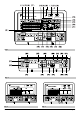
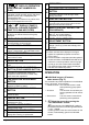
NAMES AND FUNCTIONS OF THE OPERATING SECTION (Fig. 1, 2) 1 2 UNIFIED OPERATION BUTTON “ ” DISPLAY (COOLING/HEATING SELECTION PRIVILEGE NOT SHOWN) Press to operate all indoor units. 13 For zones or individual units (groups) for which UNIFIED STOP BUTTON this is displayed, cooling and heating cannot be selected. Press to stop all indoor units. OPERATION LAMP (RED) 3 Lit white any of the indoor units under control is in operation.
“ ” DISPLAY (OPERATION CODE AND UNIT NUMBER DISPLAY) 21 The method of operation (remote controller prohibited, central operation priority after-press operation priority, etc.) is displayed by the corresponding code. This displays the numbers of any indoor units which have stopped due to an error. “ ”“ ” DISPLAY (TIME TO CLEAN AIR CLEANER ELEMENT/ 22 TIME TO CLEAN AIR FILTER) Displayed to notify the user it is time to clean the air filter or air cleaner element of the group displayed.
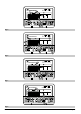
• If the zone number in the zone screen is displayed as “---,” this indicates that no units are registered in a zone. Please perform zone registration before proceeding in the zone screen. (See page 9) 䡲 Batch operation and stop method (Fig. 4) 䡲 Group operation and stop method (Fig. 5) This is for operating or stopping connected units in groups. [Group operation] 1. Press the to enter the This is for operating or stopping all connected units at once. A.
2. Select the Zone Number to be registered using the “ZONE NUMBER” button. [Batch deletion of zone registration] 1. Keeping the button pressed down will move it rapidly. 3. “ ” to the group you wish to ister using the arrow keys. reg- Keeping the button pressed down will move it rapidly. 4. Press the “SELECT” button to register that group to the zone. The “ units. ” display lights up on all the selected Pressing the “RESET” button removes the group from that zone, and “ ” goes off.
䡲 Changing the fan direction and fan strength (Fig. 8) 3. This changes the fan direction and strength settings in the air conditioner. Changing the fan direction and strength is done in the individual screen. It will scroll through “ →“ to enter the 2. individual screen. Using the arrow keys, move the “ ” to select the units to fan direction adjustment or fan strength adjustment. Keeping the button pressed down will move it rapidly. 3. Press the “FAN DIRECTION ADJUSTMENT” button.
3. When using timer operation, make sure the times do not overlap when setting the program of the schedule timer. Select the desired timer number by pressing the “TIMER NO.” button. Once the desired timer number is displayed, press the “SET” button. The display for timer number 2 will stop blinking. The “ 䡲 Setting the Operation Code (Fig. 11) [Registration] 1. ” display will disappear after 3 seconds. Select “ ” in the timer number when you do not wish to set a timer number.
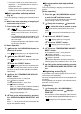
OPERATION MODE The following five operation control modes can be selected along with the temperature setting and operation mode by remote controller, for a total of twenty different modes. These twenty modes are set and displayed with control modes of 0 to 19. (For further details, see EXAMPLE OF OPERATION SCHEDULE on the next page.) • ON/OFF control impossible by remote controller..... Use this mode when operating and stopping from the central remote controller only.
Control by remote controller Operation Operation mode Unified operation, individual operation by central remote controller, or operation controlled by timer Unified stop, individual stop by central remote controller, or timer stop Temperature control Stop Rejection ON/OFF control impossible by remote controller Rejection (Example) Acceptance (Example) Rejection (Example) Rejection Rejection (Example) Only OFF control possible by remote controller Acceptance Rejection Centralized Acceptance Acce
Only OFF control possible by remote controller Programmed to operate at 8:45 Remote controller Stop --- Programmed to stop at 5:00 Programmed to operate at 5:20 --- Only stopping possible by the remote controller. Individual operation once the unit is stopped. Centralized Stop Remote controller Operation controlled by timer Timer stops even if you forget to turn off the unit. Operation controlled by timer Centralized --- Timer stops. Power reminder stops.
䡲 Setting operation mode (Fig. 12) [Registration] 1. Press the OPERATION MODE SELECTOR BUTTON. Each time you press this button, the display rotates as shown on the below list. • List of operations which can be set In the below list, “ 䡬 ” refers to the acceptable setting, while “ × ” refers to the not acceptable setting. ∗1: Setting may not be acceptable depending on the type of indoor unit with which this unit is connected.
When in zone screen The zone screen will revert to the individual screen automatically if nothing is done in it for one minute. [Registration] 1. Press the “ALL/INDIVIDUAL” button to switch to the 2. “INDIVIDUAL” screen. Using the arrow key, move the “ ” to select the unit to be monitored. Keeping the button pressed down will move it rapidly. The “ ” lights up and the status of that unit is displayed in the LCD. The cursor in the screen Fig. 13 has selected unit 2-06. code is displayed.
C4 C5 C9 CA CJ Indoor unit · remote controller sensor error E0 Outdoor unit · Safety device operation E1 Outdoor unit · PC board assembly fault E1 Outdoor unit · PC board assembly fault E3 Outdoor unit · High-pressure switch fault E4 Outdoor unit · Low-pressure switch fault E9 Outdoor unit · Electric expansion valve motor (20E) error EC Heat source unit · Intake water temperature inter-lock operation (fan operation) EF Outdoor unit · Ice thermal storage unit error F3 Outdoor unit · Discha
L6 Outdoor unit · Ground circuit for compressor motor, short circuit L8 Outdoor unit · Compressor overload, compressor motor wire disconnection L9 Outdoor unit · Compressor lock LA Outdoor unit · Power unit error LC Outdoor unit · Transmission error between inverter and outdoor control unit or M1 Central controller: PC board fault or M8 Transmission error between central controllers or MA Central controller: Incorrect combination or MC Central controller: Address setting fault P0 Insu
䡲 Setting master remote controller (Fig. 15) You must set the master remote controller of the operation mode for one of the indoor units, if two or more such indoor units with the remote controller are connected with the outdoor unit where the operation modes such as cool/heat operation and FAN operation can be set by remote controller and central remote controller. 1.
Call the unit whose system you wish to look up using the arrow keys. The “ ” on all groups in the same system as the displayed group will light up. Of those, the “ ” display in all groups which have cooling/heating selection privilege will blink. 2. Press the FILTER SIGN RESET BUTTON, and the display “ ” disappears. (Including all the groups where the air filter has been cleaned.) NOTE Be sure to check the display “ ” has disappeared at this point.
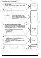
INSTALLATION TABLE When installing the equipment, mark the zone No. of each group and installation location in the below table. Setting group No. (Setting is not possible unless power is activated to both the central remote controller and indoor unit.) Operated by simplified remote controller 1. Activate power to both the central remote controller and indoor unit. 2. Remove the upper part of the remote controller. Operated by remote controller 1.
Zone No. Group No. –00 –01 –02 –03 –04 –05 –06 –07 –08 –09 –10 –11 –12 –13 –14 –15 –00 –01 –02 –03 –04 –05 –06 –07 –08 –09 –10 –11 –12 –13 –14 –15 Indoor unit Quantity of units Controlled by Location Zone No. Group No.
SPECIFICATIONS 䡲 Specifications Power supply 1 ~ 50/60Hz, 100V – 240V Power consumption Max. 8W Forced ON/OFF input Continuous “a” contact Contact current: approximately 10mA Size 180 (W) × 120 (H) × 64.5 (D) Weight 420g 䡲 Outline drawings When using this unit an electric parts box of KJB311AA is required. For installation, a steel electric parts box to be embedded is mandatory.
2 4 5 1 3 6 Fig. 9 Fig. 10 Fig. 11 Fig.
Fig. 13 Fig. 14 Fig. 15 Fig.
3P124623-8D EM05A046 (0510) HT