
Specifications


SiBE04-624_B Check
Service Diagnosis 135
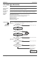
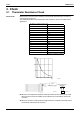
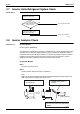
3.2 Fan Motor Connector Output Check
Check No.02 1. Check the connection of connector.
2. Check the motor power supply voltage output (pins 4 - 7).
3. Check the motor control voltage (pins 4 - 3).
4. Check the rotation command voltage (pins 4 - 2).
5. Check the rotation pulse (pins 4 - 1).
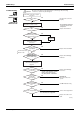
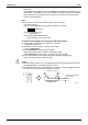
3.3 Humidity Sensor Check
Check No.07 1. Check that the connection is proper.
2. Change the ambient conditions
(*) and check that the input level changes accordingly.
* Change the humidity, temperature, airflow rate. To do this, merely breathe upon.
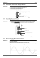
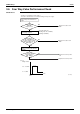
3.4 Power Supply Waveforms Check
Check No.11 Measure the power supply waveform between No. 1 and No. 2 on the terminal board, and check
the waveform disturbance.
Check to see if the power supply waveform is a sine wave. (Fig.1)
Check to see if there is waveform disturbance near the zero cross. (sections circled in Fig.2)
7
6
5
4
3
2
1
S1
(R12404)
Motor power supply voltage (310 ~ 340 VDC)
Unused
Unused
GND
Motor control voltage (15 VDC)
Rotation command voltage (1~ 5 VDC)
Rotation pulse input
1
2
3
4
5
6
Buzzer
Humidity sensor
Room temperature thermistor
5V
<Humidity sensor PCB>
CN1
GND
12V
C70
(R6023)
Fig.1 Fig.2
(R1736)
(R1444)