
Service manual


Indoor Unit SiUS041111
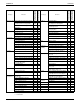
12 Printed Circuit Board Connector Wiring Diagram
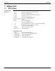
1. Indoor Unit
1.1 09/12 Class
Connectors and
Other Parts
PCB(1): Control PCB
PCB(2): Display PCB
1) S6 Connector for swing motor (horizontal blade)
2) S26 Connector for display PCB
3) S32 Connector for indoor heat exchanger thermistor
4) S200 Connector for fan motor
5) S403 Connector for adaptor PCB (option)
6) H1, H2, H3, FG Connector for terminal board
7) V1 Varistor
8) JA Address setting jumper
Refer to page 225 for detail.
JB Fan speed setting when compressor stops for thermostat OFF
JC Power failure recovery function (auto-restart)
Refer to page 227 for detail.
9) LED A LED for service monitor (green)
10)FU1 (F1U) Fuse (3.15A, 250V)
1) S27 Connector for control PCB
2) SW1 (S1W) Forced cooling operation ON/OFF button
3) LED1 (H1P) LED for operation (green)
4) LED2 (H2P) LED for timer (yellow)
5) RTH1 (R1T) Room temperature thermistor