SiUS041111 Service Manual Inverter Pair Wall Mounted Type K-Series [Applied Models] Inverter Pair : Cooling Only Inverter Pair : Heat Pump
SiUS041111 Inverter Pair Wall Mounted Type K-Series Cooling Only Indoor Unit FTXN09KEVJU FTXN12KEVJU FTXN15KVJU FTXN18KVJU FTXN24KVJU Outdoor Unit RKN09KEVJU RKN12KEVJU RKN15KEVJU RKN18KEVJU RKN24KEVJU Heat Pump Indoor Unit FTXN09KEVJU FTXN12KEVJU FTXN15KVJU FTXN18KVJU FTXN24KVJU Outdoor Unit RXN09KEVJU RXN12KEVJU RXN15KEVJU RXN18KEVJU RXN24KEVJU i Table of Contents
SiUS041111 Safety Consideration............................................................ vi Part 1 List of Functions ................................................................... 1 1. Functions.....................................................................................................2 Part 2 Specifications ....................................................................... 4 1. Specifications ...........................................................................................
SiUS041111 3.4 3.5 3.6 3.7 3.8 3.9 3.10 3.11 3.12 Discharge Pipe Temperature Control......................................................... 39 Input Current Control.................................................................................. 40 Freeze-up Protection Control ..................................................................... 41 Heating Peak-cut Control ........................................................................... 41 Outdoor Fan Control.................................
SiUS041111 4.8 4.9 4.10 4.11 4.12 4.13 4.14 4.15 4.16 4.17 4.18 4.19 4.20 4.21 4.22 4.23 4.24 Outdoor Unit PCB Abnormality................................................................... 89 OL Activation (Compressor Overload) ....................................................... 90 Compressor Lock ....................................................................................... 91 DC Fan Lock ..............................................................................................
SiUS041111 2.3 2.4 2.5 2.6 Removal of Horizontal Blades / Vertical Blades ....................................... 155 Removal of Electrical Box / PCBs / Swing Motors ................................... 157 Removal of Indoor Heat Exchanger ......................................................... 162 Removal of Fan Motor / Fan Rotor........................................................... 165 3. Outdoor Unit: 09/12 Class.......................................................................167 3.1 3.
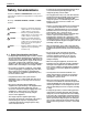
SiUS041111 Safety Considerations Read these SAFETY CONSIDERATIONS carefully before performing any repair work. Comply with these safety symbols without fail. Meanings of DANGER, WARNING, CAUTION, and NOTE Symbols: DANGER .............. Indicates an imminently hazardous situation which, if not avoided, will result in death or serious injury. WARNING ............ Indicates a potentially hazardous situation which, if not avoided, could result in death or serious injury. CAUTION .............
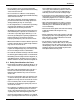
SiUS041111 • Do not repair the electrical components with wet hands. Working on the equipment with wet hands may cause an electrical shock. • Do not clean the air conditioner or heat pump by splashing water on it. Washing the unit with water may cause an electrical shock. • Turn off the power when cleaning the equipment to prevent internal fans that rotate at high speed from starting suddenly as they can cause injury. • Let the refrigerant lines cool down before performing any repair work.
SiUS041111 Part 1 List of Functions 1. Functions.....................................................................................................
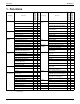
Functions SiUS041111 Operation Limit for Cooling (°FDB) Compressor Comfortable Airflow Comfort Control Operation Lifestyle Convenience 50 ~ 50 ~ 114.8 114.8 FTXN09/12KEVJU RXN09/12KEVJU Basic Function Inverter (with Inverter Power Control) FTXN09/12KEVJU RKN09/12KEVJU Functions FTXN09/12KEVJU RXN09/12KEVJU Category FTXN09/12KEVJU RKN09/12KEVJU 1.
Basic Function Inverter (with Inverter Power Control) Operation Limit for Cooling (°FDB) Operation Limit for Heating (°FWB) Compressor Comfortable Airflow Comfort Control Operation Lifestyle Convenience 50 ~ 50 ~ 114.8 114.
SiUS041111 Part 2 Specifications 1. Specifications ..............................................................................................5 1.1 Cooling Only................................................................................................. 5 1.2 Heat Pump ...................................................................................................
SiUS041111 Specifications 1. Specifications 1.1 Cooling Only 60 Hz, 208 - 230 V Model Indoor Unit Outdoor Unit Capacity Rated (Min. ~ Max.) Running Current (Rated) Power Consumption Rated (Min. ~ Max.) Power Factor EER (Rated) (Min. ~ Max.) COP (Rated) (Min. ~ Max.) Liquid Piping Connections Gas Drain Heat Insulation Max. Interunit Piping Length Max.
Specifications SiUS041111 60 Hz, 208 - 230 V Model Indoor Unit Outdoor Unit Capacity Rated (Min. ~ Max.) Moisture Removal Running Current (Rated) Power Consumption Rated (Min. ~ Max.) Power Factor EER (Rated) (Min. ~ Max.) COP (Rated) (Min. ~ Max.) Liquid Gas Piping Connections Indoor Unit Drain Outdoor Unit Heat Insulation Max. Interunit Piping Length Max.
SiUS041111 Specifications 60 Hz, 208 - 230 V Model Indoor Unit Outdoor Unit Capacity Rated (Min. ~ Max.) Moisture Removal Running Current (Rated) Power Consumption Rated (Min. ~ Max.) Power Factor EER (Rated) (Min. ~ Max.) COP (Rated) (Min. ~ Max.) Liquid Gas Piping Connections Indoor Unit Drain Outdoor Unit Heat Insulation Max. Interunit Piping Length Max.
Specifications 1.2 SiUS041111 Heat Pump 60 Hz, 208 - 230 V Indoor Unit Model FTXN09KEVJU RXN09KEVJU Outdoor Unit Capacity Rated (Min. ~ Max.) Running Current (Rated) Power Consumption Rated (Min. ~ Max.) Power Factor EER (Rated) (Min. ~ Max.) COP (Rated) (Min. ~ Max.) Liquid Piping Connections Gas Drain Heat Insulation Max. Interunit Piping Length Max.
SiUS041111 Specifications 60 Hz, 208 - 230V Indoor Unit Model FTXN15KVJU RXN15KEVJU Outdoor Unit Capacity Rated (Min. ~ Max.) Moisture Removal Running Current (Rated) Power Consumption Rated (Min. ~ Max.) Power Factor EER (Rated) (Min. ~ Max.) COP (Rated) (Min. ~ Max.) Liquid Gas Piping Connections Indoor Unit Drain Outdoor Unit Heat Insulation Max. Interunit Piping Length Max.
Specifications SiUS041111 60 Hz, 208 - 230V Indoor Unit Model Capacity Rated (Min. ~ Max.) Moisture Removal Running Current (Rated) Power Consumption Rated (Min. ~ Max.) Power Factor EER (Rated) (Min. ~ Max.) COP (Rated) (Min. ~ Max.) Liquid Gas Piping Connections Drain Indoor Unit Outdoor Unit Heat Insulation Max. Interunit Piping Length Max. Interunit Height Difference kW Btu/h kcal/h L/h A Cooling 6.45 (1.7 ~ 6.45) 22,000 (5,800 ~ 22,000) 5,550 (1,460 ~ 5,550) 4.5 12.51 - 11.32 Heating 7.03 (1.
SiUS041111 Part 3 Printed Circuit Board Connector Wiring Diagram 1. Indoor Unit.................................................................................................12 1.1 09/12 Class ................................................................................................ 12 1.2 15/18/24 Class ........................................................................................... 14 2. Outdoor Unit......................................................................................
Indoor Unit SiUS041111 1. Indoor Unit 1.1 09/12 Class Connectors and Other Parts PCB(1): Control PCB 1) 2) 3) 4) 5) 6) 7) 8) S6 S26 S32 S200 S403 H1, H2, H3, FG V1 JA JB JC 9) LED A 10)FU1 (F1U) Connector for swing motor (horizontal blade) Connector for display PCB Connector for indoor heat exchanger thermistor Connector for fan motor Connector for adaptor PCB (option) Connector for terminal board Varistor Address setting jumper Refer to page 225 for detail.
SiUS041111 PCB Detail Indoor Unit PCB(1): Control PCB FU1 S200 LED A S32 H1 V1 H3 S26 H2 FG S6 JA JC JB S403 2P206569-4 PCB(2): Display PCB S27 SW1 LED2 LED1 (Solder side) RTH1 3P206563-1 Printed Circuit Board Connector Wiring Diagram 13
Indoor Unit 1.2 SiUS041111 15/18/24 Class Connectors and Other Parts PCB (1): Control PCB 1) 2) 3) 4) 5) 6) 7) 8) S1 S6 S21 S26 S28 S32 H1, H2, H3, FG JA JB JC 9) LED A 10)FU1 11)V1 Connector for DC fan motor Connector for swing motor (horizontal blades) Connector for centralized control (HA) Connector for buzzer PCB Connector for signal receiver PCB Indoor heat exchanger thermistor Connector for terminal board Address setting jumper Refer to page 225 for detail.
SiUS041111 PCB Detail Indoor Unit PCB (1): Control PCB H2 H3 FG S1 S32 V1 FU1 H1 S21 S6 LED A JA JB JC S28 PCB (2): Signal Receiver PCB S26 2P099167-2 PCB (3): Buzzer PCB S27 SW1 S38 S29 2P099167-2 RTH1 2P099167-2 PCB (4): Display PCB LED1 LED2 S37 2P099167-2 LED3 does not function.
Outdoor Unit SiUS041111 2. Outdoor Unit 2.1 09/12 Class Connectors and Other Parts PCB(1): Filter PCB 1) 2) 3) 4) 5) 6) 7) 8) S11 AC1, AC2, S E1, E2 HL2, HN2 HR1 FU1 FU3 V2, V3 Connector for main PCB Connector for terminal board Terminal for ground Connector for main PCB Connector for reactor Fuse (3.
SiUS041111 PCB Detail Outdoor Unit PCB(1): Filter PCB HR1 HN2 E1, E2 AC2 V2 V3 S11 AC1 FU3 S HL2 FU1 3P257381-1 PCB(2): Main PCB S10 S90 LED A S70 S40 S20 S80 HL3 V1 WV U HN3 FU2 Printed Circuit Board Connector Wiring Diagram HR2 2P257375-2 17
Outdoor Unit 2.2 SiUS041111 15/18/24 Class Connectors and Other Parts PCB (1): Filter PCB 1) 2) 3) 4) 5) 6) 7) 8) 9) S11 HL1, HN1, S E1, E2 HL2, HN2 HL4, HN4 FU1 FU3 V2, V3 SW1 Connector for [S10] on main PCB Connector for terminal board Terminal for ground Connector for [HL3] [HN3] on main PCB Connector for [S12] on main PCB Fuse (3.
SiUS041111 PCB Detail Outdoor Unit PCB (1): Filter PCB FU3 V2 V3 S HL1 HN1 SW1 FU1 HN4, HL4 HN2 HL2 E2, E1 S11 3P273862-1 PCB (2): Main PCB S80 S70 FU2 S20 S40 S90 S10 S12 LED A V1 U, V, W HN3 Printed Circuit Board Connector Wiring Diagram HL3 2P273854-1 19
SiUS041111 Part 4 Function and Control 1. Main Functions..........................................................................................21 1.1 1.2 1.3 1.4 1.5 1.6 1.7 1.8 1.9 1.10 1.11 Temperature Control .................................................................................. 21 Frequency Principle.................................................................................... 21 Airflow Direction Control.............................................................................
SiUS041111 Main Functions 1. Main Functions 1.1 Temperature Control Definitions of Temperatures The definitions of temperatures are classified as following.
Main Functions Inverter Principle SiUS041111 To regulate the capacity, a frequency control is needed. The inverter makes it possible to vary the rotation speed of the compressor. The following table explains the conversion principle: Phase 1 2 Drawing of Inverter Description The supplied AC power source is converted into the DC power source for the present. The DC power source is reconverted into the three phase AC power source with variable frequency.
SiUS041111 Frequency Limits Main Functions The following functions regulate the minimum and maximum frequency: Frequency Low High Forced Cooling Operation 1.3 Functions Four-way valve operation compensation. Refer to page 37. Compressor protection function. Refer to page 37. Discharge pipe temperature control. Refer to page 39. Input current control. Refer to page 40. Freeze-up protection control. Refer to page 41. Heating peak-cut control. Refer to page 41. Defrost control.
Main Functions 1.4 SiUS041111 Fan Speed Control for Indoor Unit Outline Phase control and fan speed control contains 9 steps: LLL, LL, SL, L, ML, M, MH, H, and HH. The airflow rate can be automatically controlled depending on the difference between the room thermistor temperature and the target temperature. This is done through phase control and Hall IC control. For more information about Hall IC, refer to the troubleshooting for fan motor on page 82.
SiUS041111 COMFORT AIRFLOW Operation 1.5 Main Functions 09/12 class The fan speed is controlled automatically. The latest command has the priority between POWERFUL and COMFORT AIRFLOW. Program Dry Operation Outline Program dry operation removes humidity while preventing the room temperature from lowering. Since the microcomputer controls both the temperature and airflow rate, the temperature adjustment and fan adjustment buttons are inoperable in this mode.
Main Functions 1.6 Outline Detail SiUS041111 Automatic Operation Automatic Cooling / Heating Function When the AUTO mode is selected with the remote controller, the microcomputer automatically determines the operation mode as cooling or heating according to the room temperature and the set temperature at start-up, and automatically operates in that mode. The unit automatically switches the operation mode to maintain the room temperature at the set temperature.
SiUS041111 1.7 Main Functions Thermostat Control Thermostat control is based on the difference between the room thermistor temperature and the target temperature. Thermostat OFF Condition The temperature difference is in the zone A. Thermostat ON Condition The temperature difference returns to the zone C after being in the zone A. The system resumes from defrost control in any zones except A. The operation turns on in any zones except A.
Main Functions 1.8 SiUS041111 NIGHT SET Mode Outline When the OFF timer is set, the NIGHT SET Mode is automatically activated. The NIGHT SET Mode keeps the airflow rate setting. Detail The NIGHT SET Mode continues operation at the target temperature for the first one hour, then automatically raises the target temperature slightly in the case of cooling, or lowers it slightly in the case of heating.
SiUS041111 1.9 Main Functions ECONO Operation 09/12 class The "ECONO operation" reduces the maximum operating current and the power consumption. This operation is particularly convenient for energy-saving-oriented users. It is also a major bonus for those whose breaker capacities do not allow the use of multiple electrical devices and air conditioners. It is easily activated from the wireless remote controller by pushing the ECONO button.
Main Functions SiUS041111 1.10 Inverter POWERFUL Operation Outline In order to exploit the cooling and heating capacity to full extent, operate the air conditioner by increasing the indoor fan rotating speed and the compressor frequency. Detail When POWERFUL button is pressed, the fan speed and target temperature are converted to the following states for 20 minutes.
SiUS041111 Main Functions 1.11 Other Functions 1.11.1 Hot-Start Function In order to prevent the cold air blast that normally comes when heating operation is started, the temperature of the indoor heat exchanger is detected, and either the airflow is stopped or is made very weak thereby carrying out comfortable heating of the room. *The cold air blast is also prevented using a similar control when the defrosting operation is started or when the thermostat is turned ON. 1.11.
Function of Thermistor SiUS041111 2. Function of Thermistor RKN09/12KEVJU RKN15/18/24KEVJU RXN09/12/15/18/24KEVJU Electronic expansion valve (1) Electronic expansion valve (1) (3) (3) Four-way valve (2) Compressor (R14721) (2) Compressor (R14247) (1) Outdoor Heat Exchanger Thermistor 1. The outdoor heat exchanger thermistor is used for controlling target discharge pipe temperature.
SiUS041111 Control Specification 3. Control Specification 3.1 Mode Hierarchy Outline There are two modes; the one is the normal operation mode and the other is the forced operation mode for installation and servicing.
Control Specification 3.2 Outline SiUS041111 Frequency Control Frequency is determined according to the difference between the room thermistor temperature and the target temperature. The function is explained as follows. 1. How to determine frequency 2. Frequency command from the indoor unit (Difference between the room thermistor temperature and the target temperature) 3. Frequency initial setting 4.
SiUS041111 Control Specification 2. Determine upper limit frequency The minimum value is set as an upper limit frequency among the frequency upper limits of the following functions: Compressor protection, input current, discharge pipe temperature, heating peak-cut, freeze-up protection, defrost. 3.
Control Specification 3.3 SiUS041111 Controls at Mode Changing / Start-up 3.3.1 Preheating Operation Outline The inverter operation in open phase starts with the conditions of the preheating command from the indoor unit, the outdoor temperature, and the discharge pipe temperature. Detail 09/12 class Outdoor temperature 7°C (44.6°F) Control A (preheating for normal state) Outdoor temperature < 7°C (44.
SiUS041111 Control Specification 3.3.3 Four-Way Valve Operation Compensation Outline At the beginning of the operation as the four-way valve is switched, the differential pressure to activate the four-way valve is acquired by having output frequency which is more than a certain fixed frequency, for a certain fixed time. Detail Starting Conditions 1. When starting compressor for heating 2. When the operation mode changes from heating to cooling 3. When starting compressor for defrosting 4.
Control Specification SiUS041111 15/18/24 class (Hz) Frequency D C B A E F G H (sec.
SiUS041111 3.4 Control Specification Discharge Pipe Temperature Control Outline The discharge pipe temperature is used as the internal temperature of the compressor. If the discharge pipe temperature rises above a certain level, the upper limit of frequency is set to keep this temperature from going up further.
Control Specification 3.5 Outline SiUS041111 Input Current Control The microcomputer calculates the input current during the compressor is running, and sets the frequency upper limit from the input current. In case of heat pump model, this control which is the upper limit control of the frequency takes priority to the lower limit of control of four-way valve operation compensation.
SiUS041111 3.6 Control Specification Freeze-up Protection Control Outline During cooling operation, the signal sent from the indoor unit controls the operating frequency limitation and prevents freezing of the indoor heat exchanger. (The signal from the indoor unit is divided into zones.) Detail The operating frequency limitation is judged with the indoor heat exchanger temperature. Indoor heat exchanger thermistor temperature (Reference) 13˚C (55.4˚F) 7˚C (44.6˚F) 5˚C (41˚F) 3˚C (37.
Control Specification 3.8 SiUS041111 Outdoor Fan Control 1. Fan OFF delay when stopped The outdoor fan is turned OFF 70 seconds after the compressor stops. 2. Fan ON control to cool down the electrical box The outdoor fan is turned ON when the electrical box temperature is high while the compressor is OFF. 3. Fan OFF control while defrosting The outdoor fan is turned OFF while defrosting. 4. Fan ON/OFF control when operation starts / stops The outdoor fan is turned ON when the operation starts.
SiUS041111 Control Specification 3.10 Defrost Control Outline Defrosting is carried out by the cooling cycle (reverse cycle). The defrosting time or outdoor heat exchanger temperature must be more than a certain value to finish. Detail Conditions for Starting Defrost The starting conditions are determined with the outdoor temperature and the outdoor heat exchanger temperature. The system is in heating operation. The compressor operates for 6 minutes.
Control Specification SiUS041111 15/18/24 class The judgment is made with outdoor heat exchanger temperature. (6 ~ 30°C, 42.8 ~ 86°F) 76 Hz PI control Frequency 0 Hz 50 sec. Compressor Four way valve 120 ~ 570 sec. 40 sec. ON OFF ON OFF 8 sec. Fan 8 sec.
SiUS041111 Control Specification 3.
Control Specification SiUS041111 3.11.1 Fully Closing with Power ON The electronic expansion valve is initialized when turning on the power. The opening position is set and the pressure equalization is developed. 3.11.2 Pressure Equalizing Control When the compressor is stopped, the pressure equalizing control is activated. The electronic expansion valve opens, and develops the pressure equalization. 3.11.
SiUS041111 Control Specification 3.11.7 Control for Disconnection of the Discharge Pipe Thermistor Outline The disconnection of the discharge pipe thermistor is detected by comparing the discharge pipe temperature with the condensation temperature. If the discharge pipe thermistor is disconnected, the electronic expansion valve opens according to the outdoor temperature and the operation frequency, and operates for a specified time, and then stops.
Control Specification SiUS041111 3.12 Malfunctions 3.12.1 Sensor Malfunction Detection Sensor malfunction may occur in the thermistor. Relating to Thermistor Malfunction 1. Outdoor heat exchanger thermistor 2. Discharge pipe thermistor 3. Radiation fin thermistor 4. Outdoor temperature thermistor 3.12.2 Detection of Overcurrent and Overload Outline An excessive output current is detected and, the OL temperature is observed to protect the compressor.
SiUS041111 Part 5 Operation Manual 1. System Configuration................................................................................50 2. 09/12 Class ...............................................................................................51 2.1 2.2 2.3 2.4 2.5 2.6 2.7 2.8 Remote Controller ...................................................................................... 51 AUTO · DRY · COOL · HEAT · FAN Operation ..........................................
System Configuration SiUS041111 1. System Configuration After installation and test operation of the room air conditioner are completed, the air conditioner should be handled and operated as described in the following pages. Every user should be informed on the correct method of operation and how to check if it can cool (or heat) well, and how to use it efficiently. Providing instructions to the user can reduce requests for servicing by 80%.
SiUS041111 09/12 Class 2. 09/12 Class 2.1 Remote Controller Name of Parts Remote Controller Signal transmitter Display (LCD) • Displays the current settings. (In this illustration, each section is shown with all its displays on for the purpose of explanation.) Receiver • To use the remote controller, aim the transmitter at the indoor unit. If there is anything to block signals between the unit and the remote controller, such as a curtain, the unit will not operate.
09/12 Class SiUS041111 Open the front cover MODE selector button • Selects the operation mode. (AUTO/DRY/COOL/HEAT/ FAN) Page 11 ECONO button • ECONO operation. Page 17 COMFORT button • COMFORT AIRFLOW operation. Page 15 SWING button • Adjusting the airflow direction. Page 13 OFF TIMER button Page 18 ON TIMER button Page 19 TIMER CANCEL button • Cancels the timer setting. Page 18,19 CLOCK button SELECT button • Changes the ON/OFF TIMER settings.
SiUS041111 2.2 09/12 Class AUTO · DRY · COOL · HEAT · FAN Operation AUTO · DRY · COOL · HEAT · FAN Operation The air conditioner operates with the operation mode of your choice. From the next time on, the air conditioner will operate with the same operation mode. To start operation 1. Press and select an operation mode. • Each pressing of the button advances the mode setting in sequence. COOLING ONLY model HEAT PUMP model 2. Press DRY COOL FAN AUTO DRY COOL HEAT FAN .
09/12 Class SiUS041111 To change the temperature setting Press or . • The displayed items on the LCD will change whenever either one of the buttons is pressed. COOL operation 64-90˚F (18-32˚C) HEAT operation 50-86˚F (10-30˚C) AUTO operation 64-86˚F (18-30˚C) Press to raise the temperature and press temperature. to lower the DRY or FAN operation The temperature setting is not variable.
SiUS041111 2.3 09/12 Class Adjusting the Airflow Direction and Rate Adjusting the Airflow Direction and Rate You can adjust the airflow direction to increase your comfort. To start auto swing Upper and lower airflow direction Press . • “ ” is displayed on the LCD. • The louver (horizontal blade) will begin to swing. To set the louver at desired position • This function is effective while louver is in auto swing mode. Press when the louver has reached the desired position.
09/12 Class SiUS041111 To adjust the airflow rate setting Press . • Each pressing of Auto advances the airflow rate setting in sequence. Indoor unit quiet High Middle high Low Middle low Middle • When the airflow is set to “ ”, indoor unit quiet operation will start and the noise from the unit will become quieter. • In indoor unit quiet operation, the airflow rate is set to a weak level. • In DRY operation, the airflow rate setting is not variable.
SiUS041111 2.4 09/12 Class COMFORT AIRFLOW Operation COMFORT AIRFLOW Operation The flow of air will be in the upward direction while in COOL operation and in the downward direction while in HEAT operation, which will provide a comfortable wind that will not come in direct contact with people. To start COMFORT AIRFLOW operation Press . • “ ” is displayed on the LCD. • Airflow rate is set to auto. The louver will go up. The louver will go down.
09/12 Class 2.5 SiUS041111 POWERFUL Operation POWERFUL Operation POWERFUL operation quickly maximizes the cooling (heating) effect in any operation mode. You can get the maximum capacity. To start POWERFUL operation Press during operation. • POWERFUL operation ends in 20 minutes. Then the system automatically operates again with the previous settings which were used before POWERFUL operation. •“ ” is displayed on the LCD. To cancel POWERFUL operation Press •“ again.
SiUS041111 2.6 09/12 Class ECONO Operation ECONO Operation ECONO operation is a function which enables efficient operation by limiting the maximum power consumption value. This function is useful for cases in which attention should be paid to ensure a circuit breaker will not trip when the product runs alongside other appliances. To start ECONO operation Press •“ during operation. ” is displayed on the LCD. To cancel ECONO operation Press •“ again. ” is no longer displayed on the LCD.
09/12 Class 2.7 SiUS041111 OFF TIMER Operation OFF TIMER Operation Timer functions are useful for automatically switching the air conditioner on or off at night or in the morning. You can also use OFF TIMER and ON TIMER in combination. To use OFF TIMER operation • Check that the clock is correct. If not, set the clock to the present time. 1. Press . “ “ •“ ” is displayed on the LCD. ” blinks. ” is no longer displayed on the LCD. 2. Press until the time setting reaches the point you like.
SiUS041111 2.8 09/12 Class ON TIMER Operation ON TIMER Operation To use ON TIMER operation • Check that the clock is correct. If not, set the clock to the present time. 1. Press . “ “ •“ ” is displayed on the LCD. ” blinks. ” is no longer displayed on the LCD. 2. Press until the time setting reaches the point you like. • Each pressing of either button increases or decreases the time setting by 10 minutes. Holding down either button changes the setting rapidly. 3. Press again.
15/18/24 Class SiUS041111 3. 15/18/24 Class 3.1 Remote Controller Name of Parts Remote Controller Signal transmitter Display (LCD) Receiver • Displays the current settings. (In this illustration, each section is shown with all its displays on for the purpose of explanation.) • To use the remote controller, aim the transmitter at the indoor unit. If there is anything to block signals between the unit and the remote controller, such as a curtain, the unit will not operate.
SiUS041111 15/18/24 Class Open the front cover MODE selector button • Selects the operation mode. (AUTO/DRY/COOL/HEAT/ FAN) Page 11 SWING button • Adjusting the airflow direction. Page 13 OFF TIMER button Page 16 ON TIMER button Page 17 TIMER CANCEL button • Cancels the timer setting. Page 16,17 CLOCK button SELECT button • Changes the ON/OFF TIMER settings.
15/18/24 Class 3.2 SiUS041111 AUTO · DRY · COOL · HEAT · FAN Operation AUTO · DRY · COOL · HEAT · FAN Operation The air conditioner operates with the operation mode of your choice. From the next time on, the air conditioner will operate with the same operation mode. To start operation 1. Press and select an operation mode. • Each pressing of the button advances the mode setting in sequence. COOLING ONLY model HEAT PUMP model 2. Press DRY COOL FAN AUTO DRY COOL HEAT FAN .
SiUS041111 15/18/24 Class To change the temperature setting Press or . • The displayed items on the LCD will change whenever either one of the buttons is pressed. COOL operation 64-90˚F (18-32˚C) HEAT operation 50-86˚F (10-30˚C) AUTO operation 64-86˚F (18-30˚C) Press to raise the temperature and press temperature. to lower the DRY or FAN operation The temperature setting is not variable.
15/18/24 Class 3.3 SiUS041111 Adjusting the Airflow Direction and Rate Adjusting the Airflow Direction and Rate You can adjust the airflow direction to increase your comfort. To start auto swing Upper and lower airflow direction Press . •“ ” is displayed on the LCD. • The louvers (horizontal blades) will begin to swing. To set the louvers at desired position • This function is effective while louvers are in auto swing mode. Press when the louvers have reached the desired position.
SiUS041111 15/18/24 Class To adjust the airflow rate setting Press . • Each pressing of Auto advances the airflow rate setting in sequence. Indoor unit quiet High Low Middle high Middle low Middle • When the airflow is set to “ ”, indoor unit quiet operation will start and the noise from the unit will become quieter. • In indoor unit quiet operation, the airflow rate is set to a weak level. • In DRY operation, the airflow rate setting is not variable.
15/18/24 Class 3.4 SiUS041111 POWERFUL Operation POWERFUL Operation POWERFUL operation quickly maximizes the cooling (heating) effect in any operation mode. You can get the maximum capacity. To start POWERFUL operation Press during operation. • POWERFUL operation ends in 20 minutes. Then the system automatically operates again with the previous settings which were used before POWERFUL operation. •“ ” is displayed on the LCD. To cancel POWERFUL operation Press •“ again.
SiUS041111 3.5 15/18/24 Class OFF TIMER Operation OFF TIMER Operation Timer functions are useful for automatically switching the air conditioner on or off at night or in the morning. You can also use OFF TIMER and ON TIMER in combination. To use OFF TIMER operation • Check that the clock is correct. If not, set the clock to the present time. 1. Press . “ “ •“ ” is displayed on the LCD. ” blinks. ” is no longer displayed on the LCD. 2. Press until the time setting reaches the point you like.
15/18/24 Class 3.6 SiUS041111 ON TIMER Operation ON TIMER Operation To use ON TIMER operation • Check that the clock is correct. If not, set the clock to the present time. 1. Press . “ “ •“ ” is displayed on the LCD. ” blinks. ” is no longer displayed on the LCD. 2. Press until the time setting reaches the point you like. • Each pressing of either button increases or decreases the time setting by 10 minutes. Holding down either button changes the setting rapidly. 3. Press again.
SiUS041111 Part 6 Service Diagnosis 1. Troubleshooting with LED .........................................................................73 1.1 Indoor Unit.................................................................................................. 73 1.2 Outdoor Unit ............................................................................................... 73 2. Problem Symptoms and Measures ...........................................................74 3. Service Check Function ................
SiUS041111 5.11 Outdoor Fan System Check ..................................................................... 124 5.12 Main Circuit Short Check.......................................................................... 125 5.13 Power Module Check ...............................................................................
SiUS041111 Troubleshooting with LED 1. Troubleshooting with LED 1.1 Indoor Unit Operation Lamp The operation lamp blinks when any of the following errors is detected. 1. When a protection device of the indoor or outdoor unit is activated, or when the thermistor malfunctions. 2. When a signal transmission error occurs between the indoor and outdoor units. In either case, conduct the diagnostic procedure described in the following pages.
Problem Symptoms and Measures SiUS041111 2. Problem Symptoms and Measures Symptom Check Item The unit does not operate. Check the power supply. Check the type of the indoor unit. Check the outdoor temperature. Check if the rated voltage is supplied. Check if the indoor unit type is compatible with the outdoor unit. Heating operation cannot be used when the outdoor temperature is 24°C (75.2°F) or higher, and cooling operation cannot be used when the outdoor temperature is below 10°C (50°F).
SiUS041111 Service Check Function 3. Service Check Function Check Method 1 1. When the timer cancel button is held down for 5 seconds, 00 is displayed on the temperature display screen. Timer cancel button < ARC452 Series > (R14669) 2. Press the timer cancel button repeatedly until a long beep sounds. The code indication changes in the sequence shown below. No. 1 2 3 4 5 6 7 8 9 10 11 12 Note: Service Diagnosis Code 00 U4 L5 E6 H6 H0 A6 E7 U0 F3 A5 F6 No.
Service Check Function SiUS041111 Check Method 2 1. Press the 3 buttons (TEMP, TEMP, MODE) simultaneously to enter the diagnosis mode. (R14550) The left-side number blinks. (R9430) 2. Press the TEMP or button and change the figure until you hear the beep(s). (R14551) 3. Diagnose by the sound. beep : The left-side number does not correspond with the error code. beep beep : The left-side number corresponds with the error code but the right-side number does not.
SiUS041111 Service Check Function 5. Press the TEMP or buttonand change the figure until you hear the beep(s). (R14547) 6. Diagnose by the sound. beep : The left-side number does not correspond with the error code. beep beep : The left-side number corresponds with the error code but the right-side number does not. long beep : Both the left-side and right-side numbers correspond with the error code. Error codes and description Refer to page 78. 7. Determine the error code.
Troubleshooting SiUS041111 4. Troubleshooting 4.
SiUS041111 4.2 Troubleshooting Indoor Unit PCB Abnormality A1 Remote Controller Display Method of Malfunction Detection The system checks if the circuit works properly within the microcomputer of the indoor unit. Malfunction Decision Conditions The system cannot set the internal settings.
Troubleshooting 4.3 SiUS041111 Freeze-up Protection Control or Heating Peak-cut Control Remote Controller Display A5 Method of Malfunction Detection Freeze-up protection control During cooling operation, the freeze-up protection control (operation halt) is activated according to the temperature detected by the indoor heat exchanger thermistor.
SiUS041111 Troubleshooting Troubleshooting Caution Check No.01 Refer to P.116 Be sure to turn off the power switch before connecting or disconnecting connectors, or parts may be damaged. Check the air passage. YES Is there any short circuit? Provide sufficient air passage. NO Check the air filter. Is it very dirty? YES Clean the air filter. NO Check the dust accumulation on the indoor heat exchanger. Is it very dirty? YES Clean the indoor heat exchanger. NO Check No.
Troubleshooting 4.4 SiUS041111 Fan Motor (DC Motor) or Related Abnormality Remote Controller Display A6 Method of Malfunction Detection The rotation speed detected by the Hall IC during fan motor operation is used to determine abnormal fan motor operation. Malfunction Decision Conditions The detected rotation speed does not reach the demanded rotation speed of the target tap, and is less than 50% of the maximum fan motor rotation speed.
SiUS041111 Troubleshooting Troubleshooting FTXN09/12KEVJU Caution Check No.03 Refer to P.117 Be sure to turn off the power switch before connecting or disconnecting connectors, or parts may be damaged. Turn off the power. (Unplug the power cable or turn the breaker OFF.) Note: The motor may break when the motor connector is disconnected while remaining power supply. (Turn off the power supply before connecting the connector also.) Check the connector for connection.
Troubleshooting Troubleshooting SiUS041111 FTXN15/18/24KVJU Caution Check No.02 Refer to P.117 Be sure to turn off the power switch before connecting or disconnecting connectors, or parts may be damaged. Turn off the power supply and rotate the fan by hand. Does the fan rotate smoothly? NO Replace the indoor fan motor. YES Turn the power on and start operation. Does the fan rotate? Turn off the power supply NO and disconnect the fan motor connector, then turn the power on.
SiUS041111 4.5 Troubleshooting Thermistor or Related Abnormality (Indoor Unit) Remote Controller Display C4, C9 Method of Malfunction Detection The temperatures detected by the thermistors determine thermistor errors. Malfunction Decision Conditions The thermistor input is more than 4.96 V or less than 0.04 V during compressor operation. Supposed Causes Disconnection of connector Defective thermistor Defective indoor unit PCB Troubleshooting Caution Check No.01 Refer to P.
Troubleshooting 4.6 SiUS041111 Signal Transmission Error (between Indoor Unit and Outdoor Unit) Remote Controller Display U4 Method of Malfunction Detection The data received from the outdoor unit in indoor unit - outdoor unit signal transmission is checked whether it is normal. Malfunction Decision Conditions The data sent from the outdoor unit cannot be received normally, or the content of the data is abnormal.
SiUS041111 Troubleshooting Troubleshooting Caution Check No.11 Refer to P.118 Be sure to turn off the power switch before connecting or disconnecting connectors, or parts may be damaged. Check the indoor unit - outdoor unit connection wires. Is there any wiring error? YES Correct the indoor unit - outdoor unit connection wires. NO Check the voltage of the connection wires on the indoor terminal board between No. 1 and No. 3, and between No. 2 and No. 3.
Troubleshooting 4.7 SiUS041111 Unspecified Voltage (between Indoor Unit and Outdoor Unit) Remote Controller Display UA Method of Malfunction Detection The supply power is detected for its requirements (different from pair type and multi type) by the indoor / outdoor transmission signal. Malfunction Decision Conditions The pair type and multi type are interconnected.
SiUS041111 4.8 Troubleshooting Outdoor Unit PCB Abnormality Remote Controller Display E1 Method of Malfunction Detection The system follows the microprocessor program as specified. The system checks to see if the zero-cross signal comes in properly. Malfunction Decision Conditions The microprocessor program runs out of control. The zero-cross signal is not detected.
Troubleshooting 4.9 SiUS041111 OL Activation (Compressor Overload) Remote Controller Display E5 Method of Malfunction Detection A compressor overload is detected through compressor OL. Malfunction Decision Conditions If the error repeats, the system is shut down. Reset condition: Continuous run for about 60 minutes without any other error The operating temperature condition is not specified.
SiUS041111 Troubleshooting 4.10 Compressor Lock Remote Controller Display E6 Method of Malfunction Detection A compressor lock is detected by the current waveform generated when applying high-frequency voltage to the motor. Malfunction Decision Conditions If the error repeats, the system is shut down Reset condition: Continuous run for about 11 minutes without any other error Supposed Causes Compressor locked Disconnection of compressor harness Troubleshooting Caution Check No.
Troubleshooting SiUS041111 4.11 DC Fan Lock Remote Controller Display E7 Method of Malfunction Detection An error is determined with the high-voltage fan motor rotation speed detected by the Hall IC. Malfunction Decision Conditions The fan does not start in about 15 seconds even when the fan motor is running. If the error repeats, the system is shut down.
SiUS041111 Troubleshooting 4.12 Input Overcurrent Detection Remote Controller Display E8 Method of Malfunction Detection An input overcurrent is detected by checking the input current value with the compressor running. Malfunction Decision Conditions The current exceeds about 15 A for 2.5 seconds with the compressor running. (The upper limit of the current decreases when the outdoor temperature exceeds a certain level.
Troubleshooting SiUS041111 4.13 Four-Way Valve Abnormality Remote Controller Display EA Method of Malfunction Detection The room temperature thermistor, the indoor heat exchanger thermistor, the outdoor temperature thermistor, and the outdoor heat exchanger thermistor are checked if they function within their normal ranges in each operation mode. Malfunction Decision Conditions A following condition continues over 10 minutes after operating for 5 minutes. Cooling / Dry (room thermistor temp.
SiUS041111 Troubleshooting Troubleshooting Caution Check No.01 Refer to P.116 Be sure to turn off the power switch before connecting or disconnecting connectors, or parts may be damaged. Four-way valve coil disconnected (loose)? YES Correct it. NO Check No.13 Refer to P.119 Harness out of connector? YES Reconnect it. NO Check No.14 Refer to P.119 Check the continuity of the four-way valve coil and harness. Disconnect the harness from the connector.
Troubleshooting SiUS041111 4.14 Discharge Pipe Temperature Control Remote Controller Display F3 Method of Malfunction Detection An error is determined with the temperature detected by the discharge pipe thermistor. Malfunction Decision Conditions If the temperature detected by the discharge pipe thermistor rises above A, the compressor stops. The error is cleared when the discharge pipe temperature has dropped below B.
SiUS041111 Troubleshooting Troubleshooting Caution Check No.01 Refer to P.116 Check No.12 Refer to P.118 Check No.14 Refer to P.119 Be sure to turn off the power switch before connecting or disconnecting connectors, or parts may be damaged. Check No. 01 Check the thermistors. OK Check No. 12 Check the electronic expansion valve. NG • Discharge pipe thermistor • Outdoor heat exchanger thermistor • Outdoor temperature thermistor NG Replace the defective thermistor.
Troubleshooting SiUS041111 4.15 High Pressure Control in Cooling Remote Controller Display F6 Method of Malfunction Detection High-pressure control (operation halt, frequency drop, etc.) is activated in cooling operation if the temperature sensed by the outdoor heat exchanger thermistor exceeds the limit. Malfunction Decision Conditions The temperature sensed by the outdoor heat exchanger thermistor rises above about 60°C (140°F).
SiUS041111 Troubleshooting Troubleshooting Caution Be sure to turn off the power switch before connecting or disconnecting connectors, or parts may be damaged. Check No.01 Refer to P.116 Check the installation space. Check No.12 Refer to P.118 Check No. 17 Check the installation condition. NG OK Check No.17 Refer to P.123 Check No. 19 Check the outdoor fan. NG OK Check No.18 Refer to P.124 Check No. 18 Check the discharge pressure. NG Change the installation location or direction.
Troubleshooting SiUS041111 4.16 Compressor System Sensor Abnormality Remote Controller Display H0 Method of Malfunction Detection The system checks the DC current before the compressor starts. Malfunction Decision Conditions The DC current before compressor start-up is out of the range 0.5 - 4.5 V (sensor output converted to voltage value) The DC voltage before compressor start-up is below 50 V.
SiUS041111 Troubleshooting 4.17 Position Sensor Abnormality Remote Controller Display H6 Method of Malfunction Detection A compressor start-up failure is detected by checking the compressor running condition through the position detection circuit. Malfunction Decision Conditions The compressor fails to start in about 15 seconds after the compressor run command signal is sent. If the error repeats, the system is shut down.
Troubleshooting SiUS041111 Troubleshooting Caution Check No.15 Refer to P.120 Be sure to turn off the power switch before connecting or disconnecting connectors, or parts may be damaged. Turn off the power. Check the power supply voltage. Check No.18 Refer to P.124 Voltage as rated? Check No.20 Refer to P.125 NO Correct the power supply. YES Check No. 18 Check the discharge pressure. OK? NO Replace the stop valve. YES Check No. 20 Check the short circuit of the diode bridge.
SiUS041111 Troubleshooting 4.18 DC Voltage / Current Sensor Abnormality (09/12 Class Only) Remote Controller Display H8 Method of Malfunction Detection DC voltage or DC current sensor abnormality is identified based on the compressor running frequency and the input current. Malfunction Decision Conditions The compressor running frequency is above 52 Hz. (The input current is also below 0.1 A.) If the error repeats the system is shut down.
Troubleshooting SiUS041111 4.19 Thermistor or Related Abnormality (Outdoor Unit) Remote Controller Display H9, J3, J6, P4 Method of Malfunction Detection This fault is identified based on the thermistor input voltage to the microcomputer. A thermistor fault is identified based on the temperature sensed by each thermistor. Malfunction Decision Conditions The thermistor input voltage is above 4.96 V or below 0.04 V with the power on.
SiUS041111 Troubleshooting Troubleshooting In case of “H9” “J3” “J6” Caution Check No.01 Refer to P.116 Be sure to turn off the power switch before connecting or disconnecting connectors, or parts may be damaged. Turn on the power again. Error displayed again on remote controller? NO Reconnect the connectors or thermistors. YES Check No. 01 Check the thermistor resistance value. Normal? J3 error: the discharge pipe temperature is lower than the heat exchanger temperature.
Troubleshooting SiUS041111 4.20 Electrical Box Temperature Rise Remote Controller Display L3 Method of Malfunction Detection An electrical box temperature rise is detected by checking the radiation fin thermistor with the compressor off. Malfunction Decision Conditions With the compressor off, the radiation fin temperature is above A. The error is cleared when the radiation fin temperature drops below B.
SiUS041111 Troubleshooting Troubleshooting Caution Check No.17 Refer to P.123 Be sure to turn off the power switch before connecting or disconnecting connectors, or parts may be damaged. WARNING To cool the electrical components, the outdoor fan starts when the radiation fin temperature rises above C and stops when it drops below B. Turn off the power and turn it on again. Check No.19 Refer to P.124 Error again or outdoor fan activated? YES NO Check the radiation fin temperature.
Troubleshooting SiUS041111 4.21 Radiation Fin Temperature Rise Remote Controller Display L4 Method of Malfunction Detection A radiation fin temperature rise is detected by checking the radiation fin thermistor with the compressor on. Malfunction Decision Conditions If the radiation fin temperature with the compressor on is above A. The error is cleared when the radiation fin temperature drops below B. If the error repeats, the system is shut down.
SiUS041111 Troubleshooting Troubleshooting Caution Check No.17 Refer to P.123 Be sure to turn off the power switch before connecting or disconnecting connectors, or parts may be damaged. Turn off the power and turn it on again to start the system. Check No.19 Refer to P.124 Error displayed again? YES Has PCB been replaced? NO YES NO ∗ Silicon grease Part No.: 1172698 Check the radiation fin temperature. Above A? Check if the silicon grease applied properly on the radiation fin.
Troubleshooting SiUS041111 4.22 Output Overcurrent Detection Remote Controller Display L5 Method of Malfunction Detection An output overcurrent is detected by checking the current that flows in the inverter DC section. Malfunction Decision Conditions A position signal error occurs while the compressor is running. A speed error occurs while the compressor is running. An output overcurrent signal is fed from the output overcurrent detection circuit to the microcomputer.
SiUS041111 Troubleshooting Troubleshooting Caution Check No.15 Refer to P.120 Be sure to turn off the power switch before connecting or disconnecting connectors, or parts may be damaged. ∗ An output overcurrent may result from wrong internal wiring. If the system is interrupted by an output overcurrent after the wires have been disconnected and reconnected for part replacement, check the wiring again. Check No. 17 Check the installation condition. Check No.17 Refer to P.
Troubleshooting SiUS041111 4.23 Refrigerant Shortage Remote Controller Display Method of Malfunction Detection U0 Refrigerant shortage detection I: Refrigerant shortage is detected by checking the input current value and the compressor running frequency. If the refrigerant is short, the input current is lower than the normal value. Refrigerant shortage detection II: Refrigerant shortage is detected by checking the discharge pipe temperature and the opening of the electronic expansion valve.
SiUS041111 Troubleshooting Troubleshooting Caution Check No.01 Refer to P.116 Check No.12 Refer to P.118 Be sure to turn off the power switch before connecting or disconnecting connectors, or parts may be damaged. Any thermistor disconnected? NO Stop valve closed? YES Replace them in position. ∗ Discharge pipe thermistor ∗ Indoor or outdoor heat exchanger thermistor ∗ Room temperature thermistor ∗ Outdoor temperature thermistor YES Open the stop valve. NO Check for refrigerant shortage.
Troubleshooting SiUS041111 4.24 Low-voltage Detection or Over-voltage Detection Remote Controller Display Method of Malfunction Detection U2 Low-voltage detection: An abnormal voltage drop is detected by the DC voltage detection circuit. Over-voltage detection: An abnormal voltage rise is detected by the over-voltage detection circuit. Malfunction Decision Conditions Low-voltage detection: The voltage detected by the DC voltage detection circuit is below about 200 V.
SiUS041111 Troubleshooting Troubleshooting Caution Be sure to turn off the power switch before connecting or disconnecting connectors, or parts may be damaged. Check the supply voltage. Supply voltage as specified? NO Correct the power supply. YES Check the connection of the compressor harness. Loose or disconnected? YES Reconnect it. NO (Precaution before turning on the power again) Make sure the power has been off for at least 30 seconds. Turn on the power again.
Check SiUS041111 5. Check 5.1 Thermistor Resistance Check Check No.01 Disconnect the connectors of the thermistors from the PCB, and measure the resistance of each thermistor using tester. The relationship between normal temperature and resistance is shown in the table and the graph below. Resistance (k) Thermistor temperature (°C / °F) Room temperature thermistor for 09/12 class model –20 / –4 73.4 –15 / 5 57.0 –10 / 14 44.7 –5 / 23 35.3 0 / 32 28.2 5 / 41 22.6 10 / 50 18.3 15 / 59 14.8 20 / 68 12.
SiUS041111 5.2 Check Fan Motor Connector Output Check Check No.02 FTXN15/18/24KVJU 1. Check the connection of connector. 2. Check the motor power supply voltage output (pins 4 - 7). 3. Check the motor control voltage (pins 4 - 3). 4. Check the rotation command voltage (pins 4 - 2). 5. Check the rotation pulse (pins 4 - 1). S1 Motor power supply voltage (310 ~ 340 VDC) Unused Unused GND Motor control voltage (15 VDC) Rotation command voltage (1 ~ 6 VDC) Rotation pulse 7 6 5 4 3 2 1 Check No.
Check 5.3 SiUS041111 Power Supply Waveforms Check Check No.11 Measure the power supply waveform between No. 1 and No. 2 on the terminal board, and check the waveform disturbance. Check to see if the power supply waveform is a sine wave. (Fig.1) Check to see if there is waveform disturbance near the zero cross. (sections circled in Fig.2) Fig.1 5.4 Fig.2 Electronic Expansion Valve Check Check No.12 Conduct the followings to check the electronic expansion valve (EV). 1.
SiUS041111 5.5 Check Four-Way Valve Performance Check Check No.13 Turn off the power and turn it on again. Start heating operation. S80 voltage at 208 - 230 VAC with compressor on? (Fig. 1) * Four-way valve coil Cooling / Dry : No continuity Heating : Continuity NO Replace the outdoor unit PCB. YES Disconnect the four-way valve coil from the connector and check the continuity. Four-way valve coil resistance at 1000 ~ 2000 W? NO Replace the four-way valve coil. YES Replace the four-way valve.
Check 5.7 SiUS041111 “Inverter Checker” Check Check No.15 Characteristics If an abnormal stop occurs due to compressor startup failure or overcurrent output when using inverter unit, it is difficult to judge whether it is caused by the compressor failure or other failure (control PCB, power module, etc.). The inverter checker makes it possible to judge the cause of trouble easily and securely. Connect this checker as a quasi-compressor instead of compressor and check the output of inverter.
SiUS041111 Check Step 3 09/12 class: Activate power transistor test operation from indoor unit. 1) Turn the power on. 2) Select FAN operation with the [MODE] button on the remote controller. 3) Press the 3 buttons (TEMP , TEMP , MODE) simultaneously. 00 is displayed with the left-side number blinking. 4) Press the [MODE] button. 00 is displayed with the right-side number blinking. 5) Press the [MODE] button. T is displayed. 6) Press the [ON/OFF] button. Power transistor test operation starts.
Check 5.8 SiUS041111 Rotation Pulse Check on the Outdoor Unit PCB Check No.16 09/12 class 1. Check that the voltage between the pins 10 - 11 is 15 VDC. 2. Check if the Hall IC generates the rotation pulse (0 ~ 15 VDC) 4 times between the pins 10 -12, 10 - 13, when the fan motor is manually rotated once.
SiUS041111 5.9 Check Installation Condition Check Check No.17 Installation condition check Check the allowable dimensions of the air suction and discharge area. NG Change the installation location or direction. OK Is the discharged air short-circuited? YES Change the installation location or direction. NO Is the outdoor heat exchanger very dirty? YES Clean the outdoor heat exchanger.
Check SiUS041111 5.10 Discharge Pressure Check Check No.18 Discharge pressure check High? NO Replace the compressor. YES Is the stop valve open? NO Open the stop valve. YES Is the connection pipe deformed? YES Replace the pipe installed at the site. NO Is the air filter or indoor / outdoor heat exchanger dirty? Not dirty Dirty Clean the dirty one. Replace the compressor. (R11718) 5.11 Outdoor Fan System Check Check No.19 DC motor Check the outdoor fan system.
SiUS041111 Check 5.12 Main Circuit Short Check Check No.20 Note: Check to make sure that the voltage between (+) and (–) of the diode bridge (DB1) is approx. 0 V before checking. Measure the resistance between the pins of the DB1 as below. If the resistance is or less than 1 kW, short circuit occurs on the main circuit. (–) terminal of the tester (in case of digital, (+) terminal) (+) terminal of the tester (in case of digital, (–) terminal) Resistance is OK. Resistance is NG.
Check SiUS041111 15/18/24 class 4 3 2 1 – ~ ~ + – + Tester (R14433) 5.13 Power Module Check Check No.22 Note: Check to make sure that the voltage between (+) and (–) of the diode bridge (DB1) is approx. 0 V before checking. Disconnect the compressor harness connector from the outdoor unit PCB. To disengage the connector, press the protrusion on the connector.
SiUS041111 Part 7 Removal Procedure 1. Indoor Unit: 09/12 Class..........................................................................128 1.1 1.2 1.3 1.4 1.5 1.6 1.7 1.8 1.9 Removal of Air Filters ............................................................................... 128 Removal of Horizontal Blade.................................................................... 130 Removal of Front Panel............................................................................
Indoor Unit: 09/12 Class SiUS041111 1. Indoor Unit: 09/12 Class 1.1 Removal of Air Filters Procedure Step Warning Be sure to wait for 10 minutes or more after turning off all power supplies before disassembling work. Procedure Points 1. Appearance features Warning Dangerous: High voltage A high voltage is applied to all the electric circuits of this product including thermistors.
SiUS041111 Step 3 Pull out the air filter Indoor Unit: 09/12 Class Procedure Points downward and remove it. (R11620) 3. Remove the Titanium apatite photocatalytic air-purifying filters. 1 The Titanium apatite photocatalytic airpurifying filter is attached to the back of the air filter.
Indoor Unit: 09/12 Class 1.2 SiUS041111 Removal of Horizontal Blade Procedure Warning Step 1 Open the horizontal Be sure to wait for 10 minutes or more after turning off all power supplies before disassembling work. Procedure Points blade. Horizontal blade (R11622) 2 The center shaft can be released easily by bending the blade. Unfasten the center shaft while bending the horizontal blade slightly. (R11623) Cautions for reassembling 1.
SiUS041111 Step 5 Remove the horizontal Indoor Unit: 09/12 Class Procedure Points blade.
Indoor Unit: 09/12 Class 1.3 SiUS041111 Removal of Front Panel Procedure Warning Step 1 Open the front panel Be sure to wait for 10 minutes or more after turning off all power supplies before disassembling work. Procedure Points Right side over the position where it stops. Front panel Left side (R11627) 2 Release the right rotary shaft. Right The rotary shaft on each side can be released easily by sliding each shaft inwards. Rotary shaft (R11628) 3 Release the left rotary shaft.
SiUS041111 1.4 Indoor Unit: 09/12 Class Removal of Front Grille Procedure Warning Step 1 Remove the 2 screws, Be sure to wait for 10 minutes or more after turning off all power supplies before disassembling work. Procedure Points Front grille which fix the front grille to the main body. (R11631) 2 The front grille has 3 hooks on the upper part. Refer to the removal procedure in a reverse way when reassembling.
Indoor Unit: 09/12 Class 1.5 SiUS041111 Removal of Electrical Box / Vertical Blades Procedure Step Warning Be sure to wait for 10 minutes or more after turning off all power supplies before disassembling work. Procedure 1. Disconnect the connecting wires. 1 Remove the screw of the service cover. Points Preparation Remove the front grille according to the “Removal of Front Grille”. Service cover (R14676) 2 Pull out the service cover down in the direction of the arrow.
SiUS041111 Step 5 Loosen the screws of Indoor Unit: 09/12 Class Procedure Points Terminal board the terminal board and disconnect the connecting wires. Connecting wires Connecting wires black (1) ----- power supply white (2) ----- power supply red (3) ----- transmission yellow / green ( ) ----- ground (R11639) 6 Pull out the indoor heat exchanger thermistor. Indoor heat exchanger thermistor Take care not to lose the clip of thermistor. Clip Thermistor (R11268) (R11640) 2.
Indoor Unit: 09/12 Class Step 2 SiUS041111 Procedure Disconnect the connector for the fan motor [S200]. Release the fan motor harnesses from the hook. Points [S200] Hook (R14602) (R11642) 3 Remove the screw of the electrical box. (R11643) 4 Slide the electrical box to the right first and detach the horizontal blade from the electrical box. 5 Pull the electrical box. (R11644) There is a hook on the bottom frame. When reassembling, fit the rear side of the electrical box to the hook.
SiUS041111 Step Indoor Unit: 09/12 Class Procedure 3. Remove the vertical blade assembly. 1 Unfasten the right and left hooks of the fan guard with pliers. Points Narrow the edges of the hook to unfasten it. Hook Hook Hook (R11646) Fan guard 2 (R14608) Repeat the same procedure to remove the fan guard on the other side. Unfasten the 4 hooks at the bottom. Remove the fan guard. Hook (R11647) 3 Unfasten the hooks at the upper 2 positions. A vertical blade assembly has 6 fins.
Indoor Unit: 09/12 Class Step 4 SiUS041111 Procedure Points Unfasten the 3 hooks at the shaft mounting part by pressing them with a flat screwdriver. Hook (R8022) 5 Repeat the same procedure to remove the vertical blade assembly on the other side. Remove the vertical blade assembly.
SiUS041111 1.6 Indoor Unit: 09/12 Class Removal of Swing Motor / PCBs Procedure Step Warning Be sure to wait for 10 minutes or more after turning off all power supplies before disassembling work. Procedure Points 1. Remove the shield plate (2). 1 Unfasten the hooks at the upper 2 positions of the shield plate (2). Preparation Remove the electrical box according to the “Removal of Electrical Box / Vertical Blades”.
Indoor Unit: 09/12 Class Step 2 SiUS041111 Procedure Points The connector of the swing motor has a hook. Press the hook with a flat screwdriver to unfasten it. Unfasten the hook, and disconnect the connector. (R8037) (R11651) 3. Remove the display PCB. 1 Unfasten the hook, and release the display PCB assembly. Display PCB ASSY (R11652) 2 Turn over the display PCB assembly, and unfasten the 3 hooks to remove the display PCB.
SiUS041111 Step 3 Disconnect the Indoor Unit: 09/12 Class Procedure Points connector [S27] from the display PCB. 4 The figure shows the component parts of the display PCB. [S27]: for control PCB [S27] Operation lamp ON/OFF button (Forced cooling operation ON/OFF button) TIMER lamp Signal receiver (R14604) 4. Remove the control PCB. 1 Lift the shield plate (1) and unfasten the 2 hooks. 2 Hook Slide the shield plate (1) and remove it.
Indoor Unit: 09/12 Class SiUS041111 Step 4 Procedure Points Disconnect the terminals from the terminal board with pliers. 1 : black, upper 2 : white, lower 3 : red, upper : green without sleeve, upper green with sleeve, lower (R11656) 5 Release the 4 hooks. Lift up the upper part of the control PCB and remove it. Hook Control PCB Hook 6 The figure shows the control PCB. (R11943) Refer to page 13 for detail.
SiUS041111 1.7 Indoor Unit: 09/12 Class Removal of Indoor Heat Exchanger Procedure Step Warning Be sure to wait for 10 minutes or more after turning off all power supplies before disassembling work. Procedure Points 1. Disconnect the refrigerant piping. 1 Remove the screws which fix the indoor unit to the installation plate. Preparation Remove the electrical box according to the “Removal of Electrical Box / Vertical Blades”. (R8014) 2 Lift the indoor unit with a wooden base.
Indoor Unit: 09/12 Class Step 5 SiUS041111 Procedure Points Disconnect the flare nut for liquid piping with 2 wrenches. (R8018) 2. Remove the indoor heat exchanger. 1 Remove the indoor unit from the installation plate. Liquid piping Gas piping 2 Unfasten the hook of the piping fixture on the back of the indoor unit.
SiUS041111 Indoor Unit: 09/12 Class Step 3 Widen the auxiliary Procedure piping to the extent of 10° ~ 20°. 4 Remove the screw on the left side and unfasten the hook on the rear side. Points Auxiliary piping Hook Caution When removing or reassembling the indoor heat exchanger, be sure to wear gloves or wrap it with cloth before proceeding to work or you could be injured by the fins. Hook Screw (R11269) 5 Push and unfasten the hook on the right side and lift up the indoor heat exchanger.
Indoor Unit: 09/12 Class 1.8 SiUS041111 Removal of Fan Rotor / Fan Motor Procedure Step Warning Be sure to wait for 10 minutes or more after turning off all power supplies before disassembling work. Procedure Points 1. Remove the right side panel. 1 Remove the screw of the right side panel. Preparation Remove the indoor heat exchanger according to the “Removal of Indoor Heat Exchanger”. Right side panel (R8044) 2 Unfasten the hook of the right side panel.
SiUS041111 Step Indoor Unit: 09/12 Class Procedure 2. Remove the fan rotor and the fan motor. 1 The fan motor has 3 projections on the right side. The fan rotor has a rotating shaft on the left side. Points Fan rotor Fan motor (R8047) 2 Remove the fan rotor. (R8048) 3 Press the bearing from outside. 4 Remove the bearing.
Indoor Unit: 09/12 Class Step 5 SiUS041111 Procedure Unfasten the 2 hooks of the motor cover. Points Hook Motor cover (R8051) 6 Pull out the fan motor from the fan rotor to remove. Magnet Fan motor Coil The magnet of the fan motor is united with the fan rotor. Be careful not to attract metal waste to the magnet. Keep away from the materials that can be affected by magnetic force also.
SiUS041111 1.9 Indoor Unit: 09/12 Class Exchange of Piping Direction (Drain Hose) Procedure Step 1 Remove the heat Warning Be sure to wait for 10 minutes or more after turning off all power supplies before disassembling work. Procedure Points insulation fixing screw on the right side and remove the drain hose.
Indoor Unit: 15/18/24 Class SiUS041111 2. Indoor Unit: 15/18/24 Class 2.1 Removal of Air Filters / Front Panel Procedure Step Warning Be sure to wait for 10 minutes or more after turning off all power supplies before disassembling work. Procedure Points Warning Dangerous: High voltage A high voltage is applied to all the electric circuits of this product including thermistors.
SiUS041111 Step Indoor Unit: 15/18/24 Class Procedure Points 2. Remove the Titanium apatite photocatalytic airpurifying filters. 1 Push up the bottom of the Titanium apatite photocatalytic airpurifying filter to unfasten the hooks (2 on lower, 3 on upper) and take the filter out. The right and left filters are interchangeable.
Indoor Unit: 15/18/24 Class Step SiUS041111 Procedure Points 3. Remove the front panel. 1 While opening the front panel further than it stops, release both the shafts and remove the front panel. Slide the front panel from side to side to release each shaft. When reassembling the front panel, fit the right and left rotary shafts one by one into the grooves and fully push them in position.
SiUS041111 2.2 Indoor Unit: 15/18/24 Class Removal of Front Grille Procedure Step Warning Be sure to wait for 10 minutes or more after turning off all power supplies before disassembling work. Procedure Points 1. Remove the service cover. 1 Remove the screw and remove the service cover. Preparation Remove the front panel according to "Removal of the Air Filters / Front Panel". Service cover (R2756) You can remove the front grille without detaching the service cover. 2.
Indoor Unit: 15/18/24 Class Step 2 SiUS041111 Procedure Unfasten the 3 hooks on the top of the front grille. Points The convex marks (...) on the front panel indicate the position of the hooks. Hook (R2759) Hook (R2760) 3 154 Pull the upper part of the front grille out and lift the lower part up, and then remove the front grille. Make sure that all the 3 hooks are engaged securely when reassembling.
SiUS041111 2.3 Indoor Unit: 15/18/24 Class Removal of Horizontal Blades / Vertical Blades Procedure Step Warning Be sure to wait for 10 minutes or more after turning off all power supplies before disassembling work. Procedure Points 1. Remove the horizontal blades. 1 Open the horizontal blades. Horizontal blade (R6703) 2 Bend the horizontal blade slightly and release the center shaft. (2 locations) Remove both the horizontal blades (upper and lower) in the same way.
Indoor Unit: 15/18/24 Class Step SiUS041111 Procedure 2. Remove the vertical blades. 1 Release the right and left shafts. Points Remove the fan guards beforehand. The unit has 3 sets of vertical blades linked one another with interlock rods. Vertical blade (R6705) 2 Unfasten the 3 hooks for each set of vertical blades. Hook (R2768) 3 Pull the vertical blades rightward and remove them.
SiUS041111 2.4 Indoor Unit: 15/18/24 Class Removal of Electrical Box / PCBs / Swing Motors Procedure Step Warning Be sure to wait for 10 minutes or more after turning off all power supplies before disassembling work. Procedure Points 1. Remove the electrical box. 1 Preparation Remove the front grille according to the “Removal of Front Grille”. Remove the screw and remove the drip proof plate. Drip proof plate (R2771) 2 Cut the clamp.
Indoor Unit: 15/18/24 Class Step 6 SiUS041111 Procedure Remove the screw and remove the terminal board. Points You can remove the electrical box without detaching the terminal board. Terminal board Screw: M4 × 30 (R2773) 7 Disconnect the connector for the fan motor [S1]. [S1] (R2774) 8 Disconnect the connector for the swing motor [S6]. [S6]: for horizontal blades [S6] (R14254) 9 Remove the screw of the electrical box.
SiUS041111 Step 10 Dislocate the electrical Indoor Unit: 15/18/24 Class Procedure Points The electrical box has a hook on its back. box to the left and unfasten the back hook. 11 Catch the back hook of the electrical box when reassembling. Pull the electrical box out. 2. Remove the PCBs. 1 Remove the screw on the electrical box. 2 Pull the shield plate and release the hook. Screw: M4 × 16 The shield plate also has 2 hooks on the upper side.
Indoor Unit: 15/18/24 Class Step 3 SiUS041111 Procedure Points Press the signal receiver unit down and unfasten the hooks on the upper side, and then unfasten the hooks on the lower side. Signal receiver unit (R14255) 4 Cut the clamp. 5 The signal receiver unit has 3 PCBs. Unfasten the hooks and remove each PCB. Disconnect every connector from each PCB. Signal receiver PCB Buzzer PCB 6 160 Display PCB Remove the signal receiver unit while pushing the hooks of connectors.
SiUS041111 Step 7 Unfasten the 2 hooks on the lower side, and then the 2 hooks on the upper side. Remove the control PCB. Indoor Unit: 15/18/24 Class Procedure Points Upper hook Control PCB Lower hook (R2785) [S1]: DC fan motor [S6]: swing motor for horizontal blades [S26]: buzzer PCB [S28]: signal receiver PCB [S32]: indoor heat exchanger thermistor [S1] Refer to page 15 for detail. [S6] [S26] [S32] [S28] (R14257) 3. Remove the swing motor for horizontal blades.
Indoor Unit: 15/18/24 Class 2.5 SiUS041111 Removal of Indoor Heat Exchanger Procedure Step Warning Be sure to wait for 10 minutes or more after turning off all power supplies before disassembling work. Procedure Points 1. Disconnect the refrigerant piping. 1 Hold the indoor unit up with a piece of wood etc. 2 Preparation Remove the electrical box according to the “Removal of Electrical Box / PCBs / Swing Motors”.
SiUS041111 Step Indoor Unit: 15/18/24 Class Procedure Points 2. Remove the indoor unit. 1 Remove the indoor unit from the installation plate. 3. Remove the indoor heat exchanger. 1 Unfasten the hook of the piping fixture at the back of the indoor unit and pull out the piping. Piping fixture (R2798) 2 Widen the auxiliary piping to the extent of 10° ~ 20°.
Indoor Unit: 15/18/24 Class Step 3 SiUS041111 Procedure Points Unfasten the hooks on the left side. Hook Caution When removing or reassembling the indoor heat exchanger, be sure to wear protective gloves or wrap the indoor heat exchanger with cloths or you may be injured by the fins. (R13231) 4 Push the hooks on the right side and unfasten them. Hook (R13232) 5 Pull the indoor heat exchanger to the front side and unfasten the hooks completely, and then lift it.
SiUS041111 2.6 Indoor Unit: 15/18/24 Class Removal of Fan Motor / Fan Rotor Procedure Step Warning Be sure to wait for 10 minutes or more after turning off all power supplies before disassembling work. Procedure Points 1. Remove the right side plate. 1 Remove the 2 screws. You can remove the fan rotor without detaching the right side plate. Right side plate (R2803) 2 Lift the right side plate and remove it. 2. Remove the fan motor and rotor.
Indoor Unit: 15/18/24 Class Step 3 SiUS041111 Procedure Points When reassembling the fan motor and the fan rotor, provide as much as 5 mm (0.2 inch) of play between the side face of the rotor and the bottom frame. Remove the fan motor. Fan motor (R12897) 4 Remove the fan rotor. Side face of rotor Side face of bottom frame 5 mm (0.2 inch) Fan rotor (R14733) (R9582) (R2809) 5 Remove the 2 screws and remove the left side plate. Left side plate (1) Insert the fan motor with approx.
SiUS041111 Outdoor Unit: 09/12 Class 3. Outdoor Unit: 09/12 Class Note: The illustrations are for heat pump models as representative. 3.1 Removal of Outer Panels Procedure Step Warning Be sure to wait for 10 minutes or more after turning off all power supplies before disassembling work. Procedure Points 1. Appearance features (R11741) Take care not to cut your finger by the fins of the outdoor heat exchanger. (R14687) 2. Remove the panels. 1 Remove the screw of the stop valve cover.
Outdoor Unit: 09/12 Class Step SiUS041111 Procedure 2 Remove the 3 screws (right: 1 screw, left: 2 screws) and remove the top panel. 3 Remove the 5 screws of the front panel. Points Top panel Front panel 4 (R11745) Lift up the left side and unfasten the hooks. (R11746) 5 Release the right side hooks and remove the front panel.
SiUS041111 Step 6 Remove the 4 screws of the discharge grille. 7 Outdoor Unit: 09/12 Class Procedure Points Discharge grille Unfasten the 6 hooks and remove the discharge grille. (R11748) 3. Remove the shield plate and the conduit. 1 Remove the 2 screws. (R11749) 2 Remove the shield plate.
Outdoor Unit: 09/12 Class SiUS041111 Step Procedure 3 Remove the 2 screws. 4 Remove the conduit. Points (R11751) Conduit (R11752) 5 Remove the conduit mounting plate.
SiUS041111 3.2 Outdoor Unit: 09/12 Class Removal of Outdoor Fan / Fan Motor Procedure Warning Be sure to wait for 10 minutes or more after turning off all power supplies before disassembling work. Procedure Step 1. Remove the outdoor fan. 1 Remove the nut of the outdoor fan. Points Preparation Remove the panels according to the “Removal of Outer Panels”. Nut size: M6 Mark Outdoor fan 2 10 mm Remove the outdoor fan.
Outdoor Unit: 09/12 Class Procedure Step 3 SiUS041111 Remove the screw and remove the fan motor fixing frame. Points When reassembling, put the fan motor lead wire through the back of the fan motor so as not to be entangled with the outdoor fan. Fan motor fixing frame (R11945) Lead wire Outdoor fan (R3249) 4 Release the fan motor lead wire from the hooks. (R14724) 5 Remove the 3 screws and remove the fan motor.
SiUS041111 3.3 Outdoor Unit: 09/12 Class Removal of Electrical Box / PCB Procedure Warning Step Be sure to wait for 10 minutes or more after turning off all power supplies before disassembling work. Procedure Points 1. Remove the right side panel. 1 Release the outdoor temperature thermistor from the outdoor heat exchanger. Preparation Remove the panels according to the “Removal of Outer Panels”.
Outdoor Unit: 09/12 Class Step 3 SiUS041111 Procedure Points Remove the 4 screws on the right side panel. (R11762) 4 Unfasten the hook on the rear side. When reassembling, make sure to fit the hook. Hook (R11763) 5 Unfasten the hook, and remove the right side panel.
SiUS041111 Step Outdoor Unit: 09/12 Class Procedure Points 2. Remove the thermistors. 1 Release the discharge pipe thermistor. Pay attention so as not to lose the fixture for thermistor. When reassembling, do not insert the thermistor up to the dent of fixture. Fixture Dent Discharge pipe thermistor (R11765) 2 (R11740) Release the outdoor heat exchanger thermistor.
Outdoor Unit: 09/12 Class Step 4 SiUS041111 Procedure Points Cut the clamp. (R11768) 5 Release the harnesses. (R11769) 6 7 Disconnect the connector for the thermistors [S90]. [S90] : outdoor temperature thermistor, outdoor heat exchanger thermistor, discharge pipe thermistor [S90] Remove the thermistor assembly.
SiUS041111 Step Outdoor Unit: 09/12 Class Procedure 3. Remove the electrical box. 1 Disconnect the connector for the overload protector [S40]. Points [S40] (R11771) 2 The cooling only model has no harness for [S80]. Disconnect the connector for the four-way valve coil [S80]. [S80] 3 (R11772) Disconnect the connector for the electronic expansion valve coil [S20].
Outdoor Unit: 09/12 Class Step 4 SiUS041111 Procedure Points Disconnect the relay connector for the compressor motor. (R11774) 5 Release the harnesses from the hook. (R11775) 6 The electrical box can be removed by lifting itself without a screwdriver. Unfasten the hook of the electrical box from the partition plate with a flat screwdriver.
SiUS041111 Step 7 Lift and remove the Outdoor Unit: 09/12 Class Procedure Points electrical box. Electrical box (R11776) 4. Remove the control PCB. 1 Disconnect the 2 terminals of the reactor. Control PCB Reactor White Brown 2 Remove the screw of the terminal board, and pull out the terminals.
Outdoor Unit: 09/12 Class Step 3 SiUS041111 Procedure Points Cut the clamp. (R11780) 4 Remove the 3 screws and remove the reactor. Reactor (R11777) 5 Disconnect the 3 connectors for the filter PCB [S10], [HN3], [HL3].
SiUS041111 Step 6 Release the harnesses. Outdoor Unit: 09/12 Class Procedure Points (R11782) 7 Remove the 6 screws. Control PCB 8 9 (R10717) Unfasten the 2 hooks. Lift and remove the control PCB.
Outdoor Unit: 09/12 Class SiUS041111 Step 10 Procedure Feature of the control PCB [S10] Points [S10] [HN3] [HL3]: filter PCB [S20]: electronic expansion valve coil [S40]: overload protector [S70]: fan motor [S80]: four-way valve coil [S90]: thermistors [S90] [S70] [S40] [S20] [S80] [HL3] [HN3] (R11784) 5. Remove the filter PCB. 1 Remove the screw of the ground. Ground Filter PCB (R11785) 2 Cut the clamp.
SiUS041111 Step 3 Release the harnesses Outdoor Unit: 09/12 Class Procedure Points from the hook. (R11787) 4 Remove the screw.
Outdoor Unit: 09/12 Class Step 5 SiUS041111 Procedure Points Unfasten the 2 hooks. (R11789) 6 Release the harnesses. (R11790) 7 Remove the filter PCB.
SiUS041111 3.4 Outdoor Unit: 09/12 Class Removal of Sound Blankets Procedure Warning Step Be sure to wait for 10 minutes or more after turning off all power supplies before disassembling work. Procedure Points 1. Remove the partition plate. 1 Remove the 2 screws. (R11792) 2 The partition plate has a hook on the lower side. Lift and pull the partition plate and remove it. Hook Partition plate (R11793) When reassembling, fit the lower hook into the bottom frame.
Outdoor Unit: 09/12 Class Step SiUS041111 Procedure Points Since the piping ports on the sound blanket are torn easily, remove the blanket carefully. 2. Remove the sound blankets. 1 Lift and remove the sound blanket (top). Sound blanket (top) (R11794) 2 Pull the sound blanket (outer and inner 2) out. Sound blanket Sound blanket (inner 2) (outer) (R11795) 3 Since the piping ports on the sound blanket are torn easily, remove the blanket carefully. Pull the sound blanket (inner 1) out.
SiUS041111 3.5 Outdoor Unit: 09/12 Class Removal of Four-Way Valve Procedure Step Warning Be sure to wait for 10 minutes or more after turning off all power supplies before disassembling work. Procedure Points The cooling only model has no four-way valve coil. 1. Remove the peripheries. 1 Remove the screw and remove the four-way valve coil. Four way valve coil 2 Remove the terminal cover. (R11799) Terminal cover (R11797) 3 4 Disconnect the terminals of the compressor.
Outdoor Unit: 09/12 Class Step 5 SiUS041111 Procedure Points Remove the electronic expansion valve coil. Electronic expansion valve coil (R11798) 6 Remove the putty.
SiUS041111 Step Outdoor Unit: 09/12 Class Procedure Points Before working, make sure that the refrigerant gas is empty in the circuit. Be sure to apply nitrogen replacement when heating up the brazed part. 2. Remove the four-way valve. 1 Heat up the brazed point (a) and withdraw the piping with pliers. Warning Be careful not to burn yourself with the pipes and other parts that are heated by the gas brazing machine. (a) Warning If the refrigerant gas leaks during work, ventilate the room.
Outdoor Unit: 09/12 Class 3.6 SiUS041111 Removal of Compressor Procedure Step 1 Remove the four-way Warning Be sure to wait for 10 minutes or more after turning off all power supplies before disassembling work. Procedure Points valve, the terminal cover and disconnect the terminals of the compressor so as not to burn them. Remove the 3 nuts of the compressor. Before working, make sure that the refrigerant gas is empty in the circuit.
SiUS041111 Outdoor Unit: 15/18/24 Class 4. Outdoor Unit: 15/18/24 Class Note: The illustrations are for heat pump models as representative. 4.1 Removal of Outer Panels Procedure Step Warning Be sure to wait for 10 minutes or more after turning off all power supplies before disassembling work. Procedure 1 Remove the 3 screws and lift the top panel. 2 Remove the 4 screws and remove the discharge grille. Points Take care not to cut your finger by the fins of the outdoor heat exchanger.
Outdoor Unit: 15/18/24 Class Step 4 SiUS041111 Procedure Points Unfasten the right side hooks. (R14284) 5 When reassembling, fit the left side of the front panel first. Unfasten the left side hooks. Remove the front panel. (R14285) 6 Remove the screw of the stop valve cover.
SiUS041111 Step 7 Outdoor Unit: 15/18/24 Class Procedure Points Pull down the stop valve cover to unfasten the hooks and remove it. (R14704) The stop valve cover has 5 hooks.
Outdoor Unit: 15/18/24 Class 4.2 Removal of Outdoor Fan / Fan Motor Procedure Step 1 SiUS041111 Warning Be sure to wait for 10 minutes or more after turning off all power supplies before disassembling work. Procedure Remove the shield plate. Points Preparation Remove the top panel and the front panel according to the “Removal of Outer Panels”. Shield plate This procedure is not necessary to remove the outdoor fan only. (R14287) 2 Peel off the filament tape.
SiUS041111 Step 4 Outdoor Unit: 15/18/24 Class Procedure Release the fan motor lead wire from the groove and the 2 hooks of the partition plate. Points [S20] The harnesses of [S70] and [S20] cross each other. (R14448) (R14304) 5 Remove the nut of the outdoor fan. Nut size: M6 Outdoor fan 10 mm (R12236) (R14291) When reassembling, align mark of the outdoor fan with Dcut section of the motor shaft.
Outdoor Unit: 15/18/24 Class Step 6 SiUS041111 Procedure Points Remove the screw of the fan motor fixing frame. Fan motor fixing frame (R14293) 7 Pull down the fan motor fixing frame to unfasten the 2 hooks at the bottom. Hook 8 (R14294) Remove the fan motor fixing frame.
SiUS041111 Step 9 Outdoor Unit: 15/18/24 Class Procedure Open the hook and release the fan motor lead wire. Points Hook (R14296) 10 Remove the 4 screws and remove the fan motor.
Outdoor Unit: 15/18/24 Class 4.3 Removal of Electrical Box Procedure Step 1 SiUS041111 Warning Be sure to wait for 10 minutes or more after turning off all power supplies before disassembling work. Procedure Remove the 2 screws of the protection plate. Points Protection plate When reassembling, pass the connecting wires through the conduit and secure them with a lock nut. 12 3 (R14706) 2 Remove the protection plate.
SiUS041111 Step 5 Outdoor Unit: 15/18/24 Class Procedure Points Remove the screws and remove the connecting wires. (R14299) 6 Pull out the outdoor temperature thermistor. Outdoor temperature thermistor (R14300) 7 Remove the 6 screws of the right side panel.
Outdoor Unit: 15/18/24 Class Step 8 SiUS041111 Procedure Points When reassembling, insert the 2 lower hooks and the 1 upper hook of the back. Unfasten the 2 lower hooks and the 1 upper hook. Remove the right side panel. Hook (R14303) Hook (R14736) 9 Cut the clamp. (R14375) 10 Pull out the outdoor heat exchanger thermistor.
SiUS041111 Step Outdoor Unit: 15/18/24 Class Procedure 11 Peel off the filament tape. 12 Disconnect the connector for the fan motor [S70]. Points (R14288) [S70] (R14289) 13 Disconnect the connector for the four-way valve coil [S80]. The cooling only models have no harness for [S80].
Outdoor Unit: 15/18/24 Class Step SiUS041111 Procedure 14 Pull out the clamp. 15 Disconnect the connector for the electronic expansion valve coil [S20]. 16 Pull out the clamp. 17 Remove the wire saddle.
SiUS041111 Step 18 Outdoor Unit: 15/18/24 Class Procedure Disconnect the connector for the overload protector [S40]. Points When reassembling, insert the clamps of harnesses as below. [S40] [S40] [S80] [S20] (R14363) (R14310) 19 When reassembling, connect the connectors in the following order. (1) [S40] (2) [S20] (3) [S80] (4) [S70] The compressor harness has a clamp. When reassembling, insert the clamp as below. Pull out the clamp.
Outdoor Unit: 15/18/24 Class Step 22 SiUS041111 Procedure Disconnect the connector for the thermistors [S90]. Points [S90] (R14314) 23 Pull out the clamp. 24 Remove the wire saddle. When reassembling, insert the clamp as below. (R14315) [S90] (R14726) Wire saddle 25 (R14316) Pull out the clamp.
SiUS041111 Step 26 Outdoor Unit: 15/18/24 Class Procedure Points Remove the screw. (R14318) 27 When reassembling, insert the 2 clamps of the thermistor assembly into the holes as below. Pull out the 2 clamps at the bottom of the electrical box. (R14727) (R14320) 28 Remove the electrical box.
Outdoor Unit: 15/18/24 Class 4.4 SiUS041111 Removal of PCBs Procedure Step Warning Be sure to wait for 10 minutes or more after turning off all power supplies before disassembling work. Procedure 1. Remove the main PCB. 1 Disconnect the connector [S12] and pull out the clamp. Points [S12]: for [HL4] [HN4] on filter PCB [S12] Main PCB (R14322) 2 Disconnect the connector [S10]. [S10]: for [S11] on filter PCB [S10] (R14323) 3 Disconnect the connectors [HN3] [HL3].
SiUS041111 Step 4 Outdoor Unit: 15/18/24 Class Procedure Points When reassembling, insert the clamp as below. Pull out the clamp. [HL2] (blue) [HN2] (white) (R14325) 5 (R14728) Remove the 2 upper screws. (R14326) 6 Remove the 1 lower screw.
Outdoor Unit: 15/18/24 Class Step 7 SiUS041111 Procedure Lift the main PCB assembly. Points Main PCB Assembly (R14328) 8 Unfasten the 4 hooks at the bottom. (R14329) 9 Remove the 8 screws.
SiUS041111 Step 10 Outdoor Unit: 15/18/24 Class Procedure Points Unfasten the 2 hooks. (R14331) 11 Remove the main PCB. [S80] [S70] [S20] [S40] [S90] [S10] [S12] [HN3] [HL3] 2. Remove the radiation fin. 1 Remove the 2 screws on the bottom of the electrical box. Refer to page 19 for detail.
Outdoor Unit: 15/18/24 Class Step SiUS041111 Procedure Points 3. Remove the filter PCB. 1 Remove the ground screw. Ground 2 Pull out the terminals from the terminal board. (1): black (2): white (3): red (1) (2) (3) Terminal board 3 (R14735) (R14336) Pull out the clamp. (R14337) 4 Release the harnesses from the groove.
SiUS041111 Step 5 Outdoor Unit: 15/18/24 Class Procedure Points Remove the 2 screws. (R14365) 6 Unfasten the 3 hooks of the filter PCB assembly. (R14366) (R14367) 7 Remove the 1 screw.
Outdoor Unit: 15/18/24 Class Step 8 SiUS041111 Procedure Points Unfasten the 2 hooks. (R14369) 9 Refer to page 19 for detail. Remove the filter PCB.
SiUS041111 4.5 Outdoor Unit: 15/18/24 Class Removal of Sound Blankets Procedure Step Warning Be sure to wait for 10 minutes or more after turning off all power supplies before disassembling work. Procedure Points 1. Remove the partition plate. 1 Remove the 2 screws. (R14371) 2 Pull out the clamp from the partition plate. Partition plate (R14372) 3 Remove the partition plate. (R14373) When reassembling, insert the hook of bottom.
Outdoor Unit: 15/18/24 Class Step SiUS041111 Procedure 2. Remove the sound blankets. 1 Release the discharge pipe temperature thermistor. Points Discharge pipe temperature thermistor Since the piping ports are torn easily, remove the sound blanket carefully. Be careful not to lose the clip for the thermistor. Clip (R12287) (R14338) 2 Remove the sound blanket (top-upper). Sound blanket (top-upper) (R14339) 3 Remove the sound blanket (top-lower).
SiUS041111 Step 4 Outdoor Unit: 15/18/24 Class Procedure Sound blanket (side-outer) 5 Points Remove the sound blanket (side-outer). (R14347) Remove the sound blanket (side-inner).
Outdoor Unit: 15/18/24 Class 4.6 Removal of Electronic Expansion Valve Assembly Procedure Step 1 SiUS041111 Warning Be sure to wait for 10 minutes or more after turning off all power supplies before disassembling work. Procedure Pull out the electronic expansion valve coil. Points Electronic expansion valve coil (R14349) 2 Remove the 2 screws. Screw (R14350) Before working, make sure that the refrigerant gas is empty in the circuit.
SiUS041111 4.7 Removal of Four-Way Valve Removal of Four Way Valve Procedure Step 1 Outdoor Unit: 15/18/24 Class Warning Be sure to wait for 10 minutes or more after turning off all power supplies before disassembling work. Procedure Points Remove the screw and remove the four-way valve coil. Four-way valve coil The cooling only model has no four-way valve coil. Warning Be careful not to burn yourself with the pipes and other parts that are heated by the gas brazing machine.
Outdoor Unit: 15/18/24 Class 4.8 Removal of Compressor Procedure Step 1 SiUS041111 Warning Be sure to wait for 10 minutes or more after turning off all power supplies before disassembling work. Procedure Remove the terminal cover. Points Terminal cover (R14343) 2 Disconnect the compressor lead wires and the overload protector. Red (U) Blue (W) Yellow (V) (R14377) (R14344) 3 Remove the protection bushing.
SiUS041111 Step 4 Outdoor Unit: 15/18/24 Class Procedure Points Remove the 3 nuts of the compressor. Before working, make sure that the refrigerant gas is empty in the circuit. Be sure to apply nitrogen replacement when heating up the brazed part. (R14352) 5 6 7 Heat up the brazed part of the discharge side and disconnect. Heat up the brazed part of the suction side and disconnect. Lift the compressor up and remove it.
SiUS041111 Part 8 Trial Operation and Field Settings 1. 2. 3. 4. Pump Down Operation............................................................................221 Forced Cooling Operation .......................................................................222 Trial Operation ........................................................................................223 Field Settings ..........................................................................................224 4.1 4.2 4.3 4.4 4.
SiUS041111 Pump Down Operation 1. Pump Down Operation Outline In order to protect the environment, be sure to conduct pump down operation when relocating or disposing the unit. Detail 1) Remove the valve caps from the liquid stop valve and the gas stop valve. 2) Carry out forced cooling operation. 3) After 5 to 10 minutes, close the liquid stop valve with a hexagonal wrench. 4) After 2 to 3 minutes, close the gas stop valve and stop the forced cooling operation.
Forced Cooling Operation SiUS041111 2. Forced Cooling Operation Item Conditions Forced Cooling The forced cooling operation is allowed when both the following conditions are met. Start 1) The outdoor unit is not abnormal and not in the 3-minute standby mode. 2) The outdoor unit is not operating. The forced cooling operation starts when any of the following conditions is fulfilled. Command frequency End 1) Press the forced cooling operation ON/OFF button (SW1) on the indoor unit for 5 seconds.
SiUS041111 Trial Operation 3. Trial Operation Outline 1. Measure the supply voltage and make sure that it falls in the specified range. 2. Trial operation should be carried out in either cooling or heating mode. 3. Carry out the trial operation in accordance with the operation manual to ensure that all functions and parts, such as louver movement, are working properly. The air conditioner requires a small amount of power in its standby mode.
Field Settings SiUS041111 4. Field Settings 4.1 Model Type Setting ARC452A19, 20 This remote controller is common to the heat pump model and cooling only model. Use the DIP switch on the remote controller to set the heat pump model or cooling only model. Make the setting as shown in the illustration. (The factory set is the heat pump side.) • Heat pump model: Set the DIP switch to H/P. • Cooling only model: Set the DIP switch to C/O. DIP switch H/P 4.
SiUS041111 4.3 Field Settings When 2 Units are Installed in 1 Room When 2 indoor units are installed in 1 room, 1 of the 2 pairs of indoor unit and wireless remote controller can be set for different addresses. Both the indoor unit PCB and the wireless remote controller need alteration. Indoor Unit PCB Cut the address setting jumper JA on the control PCB.
Field Settings 4.4 SiUS041111 Facility Setting Switch (cooling at low outdoor temperature) Outline This function is limited only for facilities with air conditioning targeted toward equipment. Never use it in a residence or office where the space is occupied by people. Detail You can expand the cooling operation range from 10°C (50°F: normal operation) to –15°C (5°F: cooling at low outdoor temperature setting) by turning on the switch (SW4-B) on the outdoor unit PCB.
SiUS041111 4.5 Field Settings Jumper Settings Jumper JB (on indoor unit PCB) JC (on indoor unit PCB) Function Fan speed setting when compressor stops for thermostat OFF. (effective only at cooling operation) Power failure recovery function When connected (factory set) Fan speed setting; Remote controller setting Auto-restart When cut Fan rpm is set to “0” The unit does not resume operation after recovering from a power failure. Timer ON/OFF settings are cleared.
Application of Silicon Grease to a Power Transistor and a Diode Bridge SiUS041111 5. Application of Silicon Grease to a Power Transistor and a Diode Bridge Applicable Models All outdoor units using inverter type compressor for room air conditioner. When the printed circuit board (PCB) of an outdoor unit is replaced, it is required that silicon grease (*1) is certainly applied to the heat radiation part (the contact point to the radiation fin) of the power transistor and diode bridge.
SiUS041111 Part 9 Appendix 1. Piping Diagrams......................................................................................230 1.1 Indoor unit ................................................................................................ 230 1.2 Outdoor Unit ............................................................................................. 231 2. Wiring Diagrams......................................................................................233 2.1 Indoor Unit....................
Piping Diagrams SiUS041111 1. Piping Diagrams 1.1 Indoor unit FTXN09/12KEVJU INDOOR UNIT HEAT EXCHANGER 9/32CuT 9/32CuT 3/16CuT FIELD PIPING (1/4CuT) THERMISTOR ON HEAT EXCH. 9/32CuT 9/32CuT CROSS FLOW FAN M FAN MOTOR 3/8CuT FIELD PIPING (3/8CuT) REFRIGERANT FLOW COOLING HEATING 4D066211A FTXN15/18/24KVJU INDOOR UNIT (5/16CuT) HEAT EXCHANGER THERMISTOR ON HEAT EXCH.
SiUS041111 1.2 Piping Diagrams Outdoor Unit RKN09/12KEVJU OUTDOOR UNIT 3/16CuT M 1/4CuT 1/4CuT MOTOR OPERATED VALVE 3/16CuT MUFFLER WITH FILTER FAN MOTOR 1/4CuT 3/8CuT 3/16CuT 3/8CuT 1/4CuT PROPELLER FAN MUFFLER MUFFLER DISCHARGE PIPE THERMISTOR STRAINER HEAT EXCHANGER THERMISTOR 3/8CuT 9/32CuT HEAT EXCHANGER 9/32CuT FIELD PIPING LIQUID STOP (1/4CuT) VALVE REFRIGERANT FLOW FIELD PIPING GAS STOP (3/8CuT) VALVE 3/8CuT COMPRESSOR ACCUMULATOR COOLING 3D065937A RKN15/18/24KEVJU (16.
Piping Diagrams SiUS041111 RXN09/12KEVJU OUTDOOR UNIT OUTDOOR TEMPERATURE THERMISTOR 9/32CuT 3/16CuT M MOTOR OPERATED VALVE 1/4CuT 1/4CuT 3/16CuT MUFFLER WITH FILTER FAN MOTOR 1/4CuT HEAT EXCHANGER THERMISTOR 3/8CuT 9/32CuT HEAT EXCHANGER STRAINER 3/8CuT PROPELLER FAN 1/4CuT 3/8CuT FOUR-WAY VALVE ON : HEATING DISCHARGE PIPE THERMISTOR 3/16CuT 3/8CuT LIQUID STOP VALVE MUFFLER MUFFLER 3/8CuT COMPRESSOR GAS STOP VALVE ACCUMULATOR FIELD PIPING (1/4CuT) REFRIGERANT FLOW FIELD PIPING (
SiUS041111 Wiring Diagrams 2. Wiring Diagrams 2.1 Indoor Unit FTXN09/12KEVJU PCB 1 PCB 2 LED1 H1P LED2 H2P S27 S26 1 9 BLK BLK BLK BLK BLK BLK BLK BLK 1 9 BLK FIELD WIRING. TRANSMISSION CIRCUIT GRN/YLW FG RECTIFIER – H3 + V1 MR10 H2 H1 S1W – R1T SIGNAL RECEIVER 2 RED 3 WHT 2 BLK F1U 3.15A t˚ 3 GRN CAUTION NOTE THAT OPERATION WILL RESTART AUTOMATICALLY IF THE MAIN POWER SUPPLY IS TURNED OFF AND THEN BACK ON AGAIN.
Wiring Diagrams 2.2 SiUS041111 Outdoor Unit RKN09/12KEVJU, RXN09/12KEVJU FIELD WIRING indoor WHT BLK BRN WHT BLU GRN/YLW RED NOTE RED BLU : FUSE : LIVE L1R YLW RED WHT BLK BRN ORG BLU BLK BLK BLK BLK BLK BLK (OUTDOOR) (DISCHARGE) (CONDENSER) : DIODE BRIDGE IPM1, IPM2 L1, L2 GRY IN CASE OF HEAT PUMP TYPE IN CASE OF COOLING ONLY TYPE 1.REFER TO THE NAMEPLATE FOR THE POWER REQUIREMENTS.
Daikin Industries, Ltd.’s products are manufactured for export to numerous countries throughout the world. Daikin Industries, Ltd. does not have control over which products are exported to and used in a particular country. Prior to purchase, please therefore confirm with your local authorized importer, distributor and/or retailer whether this product conforms tot he applicable standards, and is suitable for use, in the region where the product will be used.