DAIKIN ROOM AIR CONDITIONER INSTALLATION MANUAL Français English 00_CV_3P272446-1.
Safety Precautions • Read these Safety Precautions carefully to ensure correct installation. • This manual classifies the precautions into DANGER, WARNING and CAUTION. Be sure to follow all the precautions below: they are all important for ensuring safety. DANGER ..........Indicates an imminently hazardous situation which, if not avoided, will result in death or serious injury. WARNING ........Failure to follow any of WARNING is likely to result in such grave consequences as death or serious injury.
01_EN_3P272446-1.fm Page 2 Friday, January 7, 2011 9:48 PM Safety Precautions WARNING • During pump-down, stop the compressor before removing the refrigerant piping. If the compressor is still running and the stop valve is open during pump-down, air will be sucked in when the refrigerant piping is removed, causing abnormally high pressure which could lead to equipment damage or and personal injury. • During installation, attach the refrigerant piping securely before running the compressor.
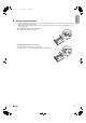
2. English 01_EN_3P272446-1.fm Page 3 Friday, January 7, 2011 9:48 PM Wireless remote controller 1) Turn on all the fluorescent lamps in the room, if any, and find the site where remote control signals are properly received by the indoor unit (within 23 feet (7m)). 2) Make the DIP switch settings. Set according to the type of unit purchased by the customer. The default settings are on the heat pump side. • For cooling only (Outdoor unit model: RKN) Set the DIP switch on the cooling only side.
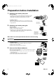
01_EN_3P272446-1.fm Page 4 Friday, January 7, 2011 9:48 PM Preparation before Installation 1. Removing and installing front panel • Removal method Hook fingers on the tabs on the left and right of the main body, and open until the panel stops. Slide the front panel sideways to disengage the rotating shaft. Then pull the front panel toward you to remove it. • Installation method Align the tabs of the front panel with the grooves, and push all the way in. Then close slowly.
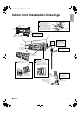
01_EN_3P272446-1.fm Page 5 Friday, January 7, 2011 9:48 PM English Indoor Unit Installation Drawings How to attach the indoor unit Hook the claws of the bottom frame to the mounting plate. If the claws are difficult to hook, remove the front grille. How to remove the indoor unit Push up the marked area (at the lower part of the front grille) to release the claws. If it is difficult to Front grille release, remove the front grille.
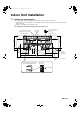
01_EN_3P272446-1.fm Page 6 Friday, January 7, 2011 9:48 PM Indoor Unit Installation 1. Installing the mounting plate • The mounting plate should be installed on a wall which can support the weight of the indoor unit. 1) Temporarily secure the mounting plate to the wall, make sure that the plate is completely level, and mark the boring points on the wall. 2) Secure the mounting plate to the wall with screws.
2. Boring a wall hole and installing wall embedded pipe • For walls containing metal frame or metal board, be sure to use a wall embedded pipe and wall cover in the feed-through hole to prevent possible heat, electrical shock, or fire. • Be sure to caulk the gaps around the pipes with caulking material to prevent water leakage. 1) Bore a feed-through hole of 2-9/16 inch (65mm) in the wall so it has a down slope toward the outside. 2) Insert a wall pipe into the hole. 3) Insert a wall cover into wall pipe.
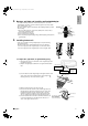
01_EN_3P272446-1.fm Page 8 Friday, January 7, 2011 9:48 PM Indoor Unit Installation 3-2. Left-side, left-back, or left-bottom piping How to replace the drain plug and drain hose Drain hose attachment position • Replacing onto the left side 1) Remove the insulation fixing screws on the right and remove the drain hose. 2) Remove the drain plug on the left side and attach it to the right side. 3) Insert the drain hose and tighten with included insulation fixing screw.
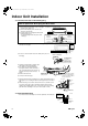
4. English 01_EN_3P272446-1.fm Page 9 Friday, January 7, 2011 9:48 PM Wiring 1) As shown in the illustration, insert the wires including the ground wire into the conduit and secure them with lock nut onto the conduit mounting plate. 2) Strip wire ends (9/16 inch (15mm)). 3) Match wire colors with terminal numbers on indoor and outdoor unit’s terminal blocks and firmly screw wires to the corresponding terminals. 4) Connect the ground wires to the corresponding terminals.
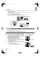
01_EN_3P272446-1.fm Page 10 Friday, January 7, 2011 9:48 PM Indoor Unit Installation 5-5. Prepare the accessory (separate product) [Figure 2]. 1) Remove the cover from the accessory (separate product). 2) Insert the connection cord into connector “S21” (white) in the accessory (separate product). 3) Route each of the connection cords through the cut-outs in the accessory, then reinstall the accessory cover in its original position.
6. Drain piping English 01_EN_3P272446-1.fm Page 11 Friday, January 7, 2011 9:48 PM The drain hose should be inclined downward. 1) Connect the drain hose, as described right. No trap is permitted. Do not put the end of the hose in water. 2) Remove the air filters and pour some water into the drain pan to check the water flows smoothly. 3) If drain hose extension or embedded drain piping is required, use appropriate parts that match the hose front end.
01_EN_3P272446-1.fm Page 12 Friday, January 7, 2011 9:48 PM Refrigerant Piping Work 2. Refrigerant piping CAUTION • Use the flare nut fixed to the main unit. (To prevent cracking of the flare nut by aged deterioration.) • To prevent gas leakage, apply refrigeration oil only to the inner surface of the flare. (Use refrigeration oil for R410A.) • Use torque wrenches when tightening the flare nuts to prevent damage to the flare nuts and gas leakage.
01_EN_3P272446-1.fm Page 13 Friday, January 7, 2011 9:48 PM 1. English Trial Operation and Testing Trial operation and testing 1-1 Measure the supply voltage and make sure that it falls in the specified range. 1-2 Trial operation should be carried out in either cooling or heating mode. For Heat pump • In cooling mode, select the lowest programmable temperature; in heating mode, select the highest programmable temperature.
00_CV_3P272446-1.fm Page 2 Tuesday, December 28, 2010 6:46 PM Two-dimensional bar code is a code for manufacturing.