Si04-402 Inverter Pair Wall Mounted Type C-Series [Applied Models] zInverter Pair : Heat Pump
Si04-402 Inverter Pair C-Series zHeat Pump Indoor Unit FTXG25CVMBW FTXG25CVMBS ATXG25CVMB FTXG35CVMBW FTXG35CVMBS ATXG35CVMB Outdoor Unit RXG25CVMB ARXG25CVMB Table of Contents RXG35CVMB ARXG35CVMB i
Si04-402 1. Introduction .............................................................................................v 1.1 Safety Cautions ........................................................................................v Part 1 List of Functions ................................................................ 1 1. List of Functions ......................................................................................2 Part 2 Specifications ........................................................
Si04-402 2.2 2.3 2.4 2.5 2.6 2.7 2.8 2.9 2.10 2.11 Names of Parts.......................................................................................43 Preparation before Operation.................................................................46 AUTO · DRY · COOL · HEAT · FAN Operation ......................................49 Adjusting the Air Flow Direction .............................................................51 POWERFUL Operation .............................................................
Si04-402 1.5 1.6 1.7 1.8 1.9 1.10 1.11 1.12 Removal of Horizontal Blade................................................................123 Removal of Reduction Motor................................................................124 Removal of Outlet Grille .......................................................................127 Removal of Vertical Blades and Swing Motor ......................................128 Removal of Electrical Box ..................................................................
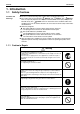
Si04-402 Introduction 1. Introduction 1.1 Safety Cautions Cautions and Warnings Be sure to read the following safety cautions before conducting repair work. The caution items are classified into “ Warning” and “ Caution”. The “ Warning” items are especially important since they can lead to death or serious injury if they are not followed closely. The “ Caution” items can also lead to serious accidents under some conditions if they are not followed.
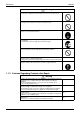
Introduction Si04-402 Warning Do not repair the electrical components with wet hands. Working on the equipment with wet hands can cause an electrical shock. Do not clean the air conditioner by splashing water. Washing the unit with water can cause an electrical shock. Be sure to provide the grounding when repairing the equipment in a humid or wet place, to avoid electrical shocks. Be sure to turn off the power switch and unplug the power cable when cleaning the equipment.
Si04-402 Introduction Warning Be sure to use an exclusive power circuit for the equipment, and follow the technical standards related to the electrical equipment, the internal wiring regulations and the instruction manual for installation when conducting electrical work. Insufficient power circuit capacity and improper electrical work can cause an electrical shock or fire. Be sure to use the specified cable to connect between the indoor and outdoor units.
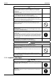
Introduction Si04-402 Warning Do not use a joined power cable or extension cable, or share the same power outlet with other electrical appliances, since it can cause an electrical shock, excessive heat generation or fire. Caution Check to see if the parts and wires are mounted and connected properly, and if the connections at the soldered or crimped terminals are secure. Improper installation and connections can cause excessive heat generation, fire or an electrical shock.
Si04-402 Part 1 List of Functions 1. List of Functions ......................................................................................
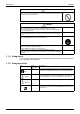
List of Functions Si04-402 { Operation Limit for Cooling (°CDB) 10 ~46 Basic Function Operation Limit for Heating (°CWB) –15 ~20 –15 ~20 { { PAM Control Compressor Comfortable Airflow Comfort Control Operation Lifestyle Convenience Health & Clean ATXG25/35CVMBW(S) ARXG25/35CVMB { 10 ~46 Inverter (with Inverter Power Control) Category FTXG25/35CVMBW(S) RXG25/35CVMB Functions ATXG25/35CVMBW(S) ARXG25/35CVMB Category FTXG25/35CVMBW(S) RXG25/35CVMB 1.
Si04-402 Part 2 Specifications 1. Specifications ..........................................................................................
Specifications Si04-402 1. Specifications 230V, 50Hz Indoor Units Model Capacity Rated (Min.~Max.) Moisture Removal Running Current (Rated) Power Consumption Rated (Min.~Max.
Si04-402 Specifications 230V, 50Hz Indoor Units Model FTXG35CVMBW RXG35CVMB Outdoor Units Capacity Rated (Min.~Max.) Moisture Removal Running Current (Rated) Power Consumption Rated (Min.~Max.
Specifications Si04-402 230V, 50Hz Indoor Units Model Capacity Rated Moisture Removal Running Current (Rated) Power Consumption Rated Power Factor COP Liquid Piping Connections Gas Drain Heat Insulation Indoor Unit Front Panel Color Air Flow Rate m³/min (cfm) Type Motor Output Speed Air Direction Control Air Filter Running Current (Rated) Power Consumption (Rated) Power Factor Temperature Control Dimensions (H×W×D) Packaged Dimensions (H×W×D) Weight Gross Weight Operation H/L Sound Sound Power H Outdoor U
Si04-402 Part 3 Printed Circuit Board Connector Wiring Diagram 1. Printed Circuit Board Connector Wiring Diagram....................................8 1.1 Indoor Unit................................................................................................8 1.2 Outdoor Unit ...........................................................................................
Printed Circuit Board Connector Wiring Diagram Si04-402 1. Printed Circuit Board Connector Wiring Diagram 1.
Si04-402 Printed Circuit Board Connector Wiring Diagram PCB Detail PCB(1): Control PCB (indoor unit) S1 S49 S41 S51 JB JA JC V1 S21 FU1 S32 S46 S36 (R3319) PCB(2): Signal Receiver PCB S47 RTH1 SW1 LED4 LED2 LED3 (R3320) PCB(3): INTELLIGENT EYE sensor PCB S36 (R3321) Printed Circuit Board Connector Wiring Diagram 9
Printed Circuit Board Connector Wiring Diagram 1.
Si04-402 PCB Detail Printed Circuit Board Connector Wiring Diagram PCB(1): Control PCB (outdoor unit) S10 S40 LEDA S90 S30 S70 HC3 FU2(3.15A) HN3 HC4 S20 S80 V1 FU1(3.
Printed Circuit Board Connector Wiring Diagram 12 Si04-402 Printed Circuit Board Connector Wiring Diagram
Si04-402 Part 4 Function and Control 1. Main Functions......................................................................................14 1.1 1.2 1.3 1.4 1.5 1.6 1.7 1.8 1.9 1.10 Frequency Principle................................................................................14 Power-Airflow Flap, Wide-Angle Louvres and Auto-Swing ....................16 Operation Starting Control......................................................................17 Fan Speed Control for Indoor Units..............
Main Functions Si04-402 1. Main Functions Note: 1.1 See the list of functions for the functions applicable to different models. Frequency Principle Main Control Parameters Additional Control Parameters Inverter Principle Drawing of Inverter The compressor is frequency-controlled during normal operation.
Si04-402 Inverter Features Main Functions The inverter provides the following features: The regulating capacity can be changed according to the changes in the outside temperature and cooling/heating load. Quick heating and quick cooling The compressor rotational speed is increased when starting the heating (or cooling). This enables a quick set temperature.
Main Functions 1.2 Si04-402 Power-Airflow Flap, Wide-Angle Louvres and AutoSwing Power-airflow Flap The large flap sends a large volume of air downwards to the floor. The flap provides an optimum control area in cooling, heating and dry mode. Heating Mode During heating mode, the large flap enables direct warm air straight downwards. The flap presses the warm air above the floor to reach the entire room. Cooling Mode During cooling mode, the flap retracts into the indoor unit.
Si04-402 1.3 Main Functions Operation Starting Control The system carries out the following control at the beginning to conduct every functional parts properly. 1. Opening the front panel fully 2. Output of the ∆D signal after the front panel starts moving 3. Opening the flap fully after the front panel opens fully 4.
Main Functions 1.4 Si04-402 Fan Speed Control for Indoor Units Control Mode The airflow rate can be automatically controlled depending on the difference between the set temperature and the room temperature. This is done through phase control and hall IC control. For more information about Hall IC, refer to the troubleshooting for fan motor on page 75. Phase Steps Phase control and fan speed control contains 9 steps: LLL, LL, SL, L, ML, M, MH, H and HH.
Si04-402 1.5 Main Functions Programme Dry Function Programme dry function removes humidity while preventing the room temperature from lowering. Since the microcomputer controls both the temperature and air flow volume, the temperature adjustment and fan adjustment buttons are inoperable in this mode. In Case of Inverter Units The microcomputer automatically sets the temperature and fan settings.
Main Functions 1.6 Si04-402 Automatic Operation Automatic Cooling / Heating Function (Heat Pump Only) When the AUTO mode is selected with the remote controller, the microcomputer automatically determines the operation mode from cooling and heating according to the room temperature and setting temperature at the time of the operation startup, and automatically operates in that mode.
Si04-402 1.7 Main Functions NIGHT SET Mode When the OFF timer is set, the NIGHT SET circuit automatically activates. The NIGHT SET circuit maintains the airflow setting made by users. NIGHT SET Circuit The NIGHT SET circuit continues heating or cooling the room at the set temperature for the first one hour, then automatically lowers the temperature setting slightly in the case of cooling, or raises it slightly in the case of heating, for economical operations.
Main Functions 1.8 Si04-402 INTELLIGENT EYE This is the function that detects existence of humans in the room by a human motion sensor (INTELLIGENT EYE) and reduces the capacity when there is no human in the room in order to save electricity. Processing 1. Detection method by INTELLIGENT EYE sampling (20msec) Sensor output 1sec If the sensor detects the outputs 10 times/sec. or more, it judges humans exist.
Si04-402 Main Functions Since the set temperature is shifted by 2°C higher for 40 minutes, compressor speed becomes low and can realize energy saving operation. But as thermostat is prone to be off by the fact that the set temperature has been shifted, the thermostat-off action is prohibited in 40 minutes so as to prevent this phenomena.
Main Functions Si04-402 1.10 Other Functions 1.10.1 Hot Start Function Heat Pump Only In order to prevent the cold air blast that normally comes when heating is started, the temperature of the heat exchanger of the indoor unit is detected, and either the air flow is stopped or is made very weak thereby carrying out comfortable heating of the room. *The cold air blast is also prevented using a similar control when the defrosting operation is started or when the thermostat gets turned ON. 1.10.
Si04-402 Function of Thermistor 2. Function of Thermistor 2.1 Heat Pump Model A C Four way valve B Compressor (R3305) A Outdoor Heat Exchanger Thermistor (DCB) 1. The outdoor heat exchanger thermistor is used for controlling target discharge temperature. Set a target discharge temperature depending on the outdoor and indoor heat exchanger temperature. Control the electronic expansion valve opening so that the target discharge temperature can be obtained. 2.
Control Specification Si04-402 3. Control Specification 3.1 Mode Hierarchy Outline There are two modes; the mode selected in user’s place (normal air conditioning mode) and forced operation mode for installation and providing service. Detail 1.
Si04-402 3.2 Control Specification Frequency Control Outline Frequency will be determined according to the difference between room and set temperature. The function is explained as follows. 1. How to determine frequency. 2. Frequency command from an indoor unit. (The difference between a room temperature and the temperature set by the remote controller.) 3. Frequency command from an indoor unit. 4. Frequency initial setting. 5. PI control.
Control Specification Si04-402 Indoor Frequency Command (∆D signal) The difference between a room temperature and the temperature set by the remote controller will be taken as the “∆D signal” and is used for frequency command. Temperature difference ∆D signal Temperature difference ∆D signal Temperature difference ∆D signal Temperature difference ∆D signal 0 2.0 4 4.0 8 6.0 C 0.5 ∗Th OFF 1 2.5 5 4.5 9 6.5 D 1.0 1.5 2 3 3.0 3.5 6 7 5.0 5.5 A B 7.0 7.
Si04-402 Control Specification 3.3.2 Four Way Valve Switching Outline of Heating Operation Heat Pump Only During the heating operation current must be conducted and during cooling and defrosting current must not be conducted. In order to eliminate the switching sound (as the four way valve coil switches from ON to OFF) when the heating is stopped, the delay switch of the four way valve must be carried out after the operation stopped.
Control Specification 3.4 Si04-402 Discharge Pipe Control Outline The discharge pipe temperature is used as the compressor's internal temperature. If the discharge pipe temperature rises above a certain level, the operating frequency upper limit is set to keep this temperature from going up further. Detail Divide the Zone Management within the Zones Zone Stop zone Drooping zone Unchanged zone Return / Reset zone 3.
Si04-402 3.6 Control Specification Freeze-up Protection Control Outline During cooling operation, the signals being sent from the indoor unit allow the operating frequency limitation and then prevent freezing of the indoor heat exchanger. (The signal from the indoor unit must be divided into the zones as the followings. Detail Conditions for Start Controlling Judge the controlling start with the indoor heat exchanger temperature after 2 sec from operation start. Control in Each Zone 3.
Control Specification 3.8 Si04-402 Fan Control Outline Fan control is carried out according to the following priority. 1. Fan control when defrosting 2. Fan OFF delay when stopped 3. ON/OFF control when cooling operation 4. Fan control when forced operation 5. Fan control in low noise mode 6. Fan control during heating operation 7. Fan control in the quiet mode 8.
Si04-402 Control Specification 3.10 Defrost Control Outline Heat Pump Only Defrosting is carried out by the cooling cycle (reverse cycle). The defrosting time or outdoor heat exchanger temperature must be more than its fixed value when finishing. Detail Conditions for Starting Defrost The starting conditions must be made with the outdoor air temperature and heat exchanger temperature.
Control Specification Si04-402 3.11 Electronic Expansion Valve Control Detail The followings are the examples of control which function in each mode by the electronic expansion valve control. Operation pattern Control for abnormally high discharge pipe temperature The following items are included in the electronic expansion valve control. Electronic expansion valve is fully closed 1. Electronic expansion valve is fully closed when turning on the power. 2. Pressure equalizing control Open Control 1.
Si04-402 Control Specification 3.11.1 Fully Closing with Power ON Initialize the electronic expansion valve when turning on the power, set the opening position and develop pressure equalizing. 3.11.2 Pressure Equalization Control When the compressor is stopped, open and close the electronic expansion valve and develop pressure equalization. 3.11.3 Opening Limit Outline Limit a maximum and minimum opening of the electronic expansion valve.
Control Specification Si04-402 3.11.7 Control when frequency is changed When the target discharge pipe temperature control is active, if the target frequency is changed for a specified value in a certain time period, cancel the target discharge pipe temperature control and change the target opening of the electronic expansion valve according to the shift. 3.11.
Si04-402 Control Specification 3.12 Malfunctions 3.12.1 Sensor Malfunction Detection Sensor malfunction may occur in the thermistor. Relating to Thermistor Malfunction 1. Outdoor heat exchanger thermistor 2. Discharge pipe thermistor 3. Fin thermistor 4. Outdoor air thermistor 3.12.2 Detection of Overload and Over Current Outline In order to protect the inverter, detect an excessive output current, and for protecting compressor, monitor the OL operation.
Control Specification Detail Si04-402 I Judgment by power consumption When an output frequency is exceeds 55 Hz and the input current is less than specified value, the adjustment is made for insufficient gas. II Judgment by discharge pipe temperature When discharge pipe temperature is 20°C higher than target value and the electronic expansion value opening is 450 pulses (max.), the adjustment is made for insufficient gas.
Si04-402 Part 5 System Configuration 1. System Configuration............................................................................40 2. Instruction..............................................................................................41 2.1 2.2 2.3 2.4 2.5 2.6 2.7 2.8 2.9 2.10 2.11 System Configuration Safety Precautions .................................................................................41 Names of Parts...........................................................................
System Configuration Si04-402 1. System Configuration After the installation and test operation of the room air conditioner have been completed, it should be operated and handled as described below. Every user would like to know the correct method of operation of the room air conditioner, to check if it is capable of cooling (or heating) well, and to know a clever method of using it.
Si04-402 Instruction 2. Instruction 2.1 Safety Precautions • • • • Keep this manual where the operator can easily find them. Read this manual attentively before starting up the unit. For safety reason the operator must read the following cautions carefully. This manual classifies precautions into WARNINGS and CAUTIONS. Be sure to follow all precautions below: they are all important for ensuring safety.
Instruction Si04-402 • Do not block air inlets nor outlets. Impaired air flow may result in insufficient performance or trouble. • Do not stand or sit on the outdoor unit. Do not place any object on the unit to avoid injury, do not remove the fan guard. • Do not place anything under the indoor or outdoor unit that must be kept away from moisture. In certain conditions, moisture in the air may condense and drip. • After a long use, check the unit stand and fittings for damage.
Si04-402 2.
Instruction Si04-402 ■ Outdoor Unit 19 21 22 20 23 ■ Indoor Unit • The operation mode refers to the following table. Temperature Air flow Mode setting rate 25°C FTXG AUTO AUTO 1. Air filter 2. Titanium Apatite Photocatalytic Air-Purifying Filter: • These filters are attached to the inside of the air filters. 3. Air inlet • This switch is useful when the remote controller is missing. 4. Top front panel 6. Panel tab 13. Room temperature sensor: • It senses the air temperature around the unit. 14.
Si04-402 Instruction ■ Remote Controller 1 2 5 3 6 4 9 7 10 8 11 13 12 14 16 17 15 < ARC433A41 > 1. Signal transmitter: • It sends signals to the indoor unit. 2. Display: • It displays the current settings. (In this illustration, each section is shown with all its displays ON for the purpose of explanation.) 3. SENSOR button: for INTELLIGENT EYE operation (page 16.) 4. POWERFUL button: for POWERFUL operation (page 14.) 5. TEMPERATURE adjustment buttons: • It changes the temperature setting.
Instruction 2.3 Si04-402 Preparation before Operation ■ To set the batteries 1. Press with a finger and slide the front cover to take it off. Position + and – correctly! 2 2. Set two dry batteries (AAA). 3. Set the front cover as before. 3 1 ATTENTION ■ About batteries • When replacing the batteries, use batteries of the same type, and replace the two old batteries together. • When the system is not used for a long time, take the batteries out.
Si04-402 Instruction ■ To operate the remote controller • To use the remote controller, aim the transmitter at the indoor unit. If there is anything to block signals between the unit and the remote controller, such as a curtain, the unit will not operate. • Do not drop the remote controller. Do not get it wet. • The maximum distance for communication is about 7 m. Receiver ■ To fix the remote controller holder on the wall 1. Choose a place from where the signals reach the unit.
Instruction Si04-402 ■ To set the clock 1. Press “CLOCK button”. is displayed. blinks. 2. Press “TIMER setting button” to set the clock to the present time. Holding down “ ” button rap” or “ idly increases or decreases the time display. 3. Press “CLOCK button”. blinks. 2 1.3 NOTE ■ Tips for saving energy • Be careful not to cool (heat) the room too much. Keeping the temperature setting at a moderate level helps save energy. • Cover windows with a blind or a curtain.
Si04-402 2.4 Instruction AUTO · DRY · COOL · HEAT · FAN Operation The air conditioner operates with the operation mode of your choice. From the next time on, the air conditioner will operate with the same operation mode. ■ To start operation 1. Press “MODE selector button” and select a operation mode. • Each pressing of the button advances the mode setting in sequence. 4 : AUTO 2, 3 1 5 : DRY : COOL : HEAT : FAN 2. Press “ON/OFF button” . • The operation lamp will light up and the panel will open.
Instruction Si04-402 ■ To change the air flow rate setting 5. Press “FAN setting button”. DRY mode AUTO or COOL or HEAT or FAN mode Five levels of air flow rate setting from “ plus “ ”“ ” to “ ” ” are available. The air flow rate setting is not variable. • Indoor unit quiet operation When the air flow is set to “ ”, the noise from the indoor unit will become quieter. Use this when making the noise quieter. The unit might lose capacity when the air flow rate is set to a weak level.
Si04-402 2.5 Instruction Adjusting the Air Flow Direction You can adjust the air flow direction to increase your comfort. ■ To adjust the horizontal blade (flap) 1. Press “SWING button • “ ”. ” is displayed on the LCD. 2. When the flap has reached the desired position, press “SWING button ” once more. • The flap will stop moving. 1, 2 3, 4 5, 6 ■ To adjust the vertical blades (louvers) 3. Press “SWING button • “ ”. ” is displayed on the LCD. 4.
Instruction Si04-402 ■ To start COMFORT AIRFLOW operation 5. Press “COMFORT AIRFLOW button”. The flap orientation will change, preventing air from blowing directly on the occupants of the room. • “ ” is displayed on the LCD. 〈COOL/DRY〉 The flap will go up. 〈HEAT〉 The flap will go down. ■ To cancel COMFORT AIRFLOW operation 6. Press “COMFORT AIRFLOW button” again. Note • When “SWING button ” is selected, the flap swinging range depends on the operation mode. (See the figure.
Si04-402 2.6 Instruction POWERFUL Operation POWERFUL operation quickly maximizes the cooling (heating) effect in any operation mode. You can get the maximum capacity . ■ To start POWERFUL operation 1. Press “POWERFUL button”. • POWERFUL operation ends in 20 minutes. Then the system automatically operates again with the settings which were used before POWERFUL operation. • When using POWERFUL operation, there are some functions which are not available. • “ 1, 2 ” is displayed on the LCD.
Instruction 2.7 Si04-402 OUTDOOR UNIT SILENT Operation OUTDOOR UNIT SILENT operation lowers the noise level of the outdoor unit by changing the frequency and fan speed on the outdoor unit. This function is convenient during night. ■ To start OUTDOOR UNIT SILENT operation 1. Press “SILENT button”. • “ ” is displayed on the LCD. ■ To cancel OUTDOOR UNIT SILENT operation 2. Press “SILENT button” again.
Si04-402 2.8 Instruction INTELLIGENT EYE Operation “INTELLIGENT EYE” is the infrared sensor which detects the human movement. ■ To start INTELLIGENT EYE operation 1. Press “SENSOR button”. • “ ” is displayed on the LCD. ■ To cancel the INTELLIGENT EYE operation 2. Press “SENSOR button” again. 1, 2 [EX.] When somebody in the room • Normal operation. • The INTELLIGENT EYE lamp lights up. When nobody in the room • 20 min. after, start energy saving operation. • The INTELLIGENT EYE lamp goes off.
Instruction Si04-402 “INTELLIGENT EYE” is useful for Energy Saving ■ Energy saving operation • Change the temperature –2°C in heating / +2°C in cooling / +2°C in dry mode from set temperature. • Decrease the air flow rate slightly in fan operation. (In FAN mode only) Notes on “INTELLIGENT EYE” • Application range is as follows. Vertical angle 90˚ (Side View) Horizontal angle 110˚ (Top View) 90˚ 7m 55˚ 55˚ 7m • Sensor may not detect moving objects further than 7m away.
Si04-402 2.9 Instruction TIMER Operation Timer functions are useful for automatically switching the air conditioner on or off at night or in the morning. You can also use OFF TIMER and ON TIMER in combination. ■ To use OFF TIMER operation • Check that the clock is correct. If not, set the clock to the present time. (page 9.) 1. Press “OFF TIMER button”. is displayed. blinks. 2. Press “TIMER Setting button” until the time setting reaches the point you like.
Instruction Si04-402 ■ To use ON TIMER operation • Check that the clock is correct. If not, set the clock to the present time (page 9.). 1. Press “ON TIMER button”. is displayed. blinks. 2. Press “TIMER Setting button” until the time setting reaches the point you like. • Every pressing of either button increases or decreases the time setting by 10 minutes. Holding down either button changes the setting rapidly. 3. Press “ON TIMER button” again. • The TIMER lamp lights up.
Si04-402 Instruction 2.10 Care and Cleaning CAUTION • Before cleaning, be sure to stop the operation and turn the breaker OFF. • Always shut down the unit (and close the panel) before doing any work. Opening the panel during operation may cause the panel to fall off. Units ■ Indoor unit, Outdoor unit and Remote controller 1. Wipe them with dry soft cloth. ■ Top front panel 1. Open the top front panel. • Open the top front panel by placing a finger on the panel tab on either side of the top front panel.
Instruction Si04-402 Filters 1. Open the top front panel. • Open the top front panel by placing a finger on the panel tab on either side of the top front panel and then secure it using the supporting plate on the right. 2. Pull out the air filters. • Push a little upwards the tab at the center of each air filter, then pull it down. Supporting plate 3. Take off the Titanium Apatite Photocatalytic Air-Purifying Filter.
Si04-402 Instruction Check Check that the base, stand and other fittings of the outdoor unit are not decayed or corroded. Check that nothing blocks the air inlets and the outlets of the indoor unit and the outdoor unit. Check that the drain comes smoothly out of the drain hose during COOL or DRY operation. • If no drain water is seen, water may be leaking from the indoor unit. Stop operation and consult the service shop if this is the case. ■ Before a long idle period 1.
Instruction Si04-402 2.11 Troubleshooting These cases are not troubles. The following cases are not air conditioner troubles but have some reasons. You may just continue using it. Case Explanation Operation does not start soon. • When ON/OFF button was pressed soon after operation was stopped. • When the mode was reselected. • This is to protect the air conditioner. You should wait for about 3 minutes. Hot air does not flow out soon after the start of heating operation.
Si04-402 Instruction Check again. Please check again before calling a repair person. Case The air conditioner does not operate. (OPERATION lamp is off) Check • Hasn’t a breaker turned OFF or a fuse blown? • Isn’t it a power failure? • Are batteries set in the remote controller? • Is the timer setting correct? Cooling (Heating) effect is poor.
Instruction Si04-402 Call the service shop immediately. WARNING ■ When an abnormality (such as a burning smell) occurs, stop operation and turn the breaker OFF. Continued operation in an abnormal condition may result in troubles, electric shocks or fire. Consult the service shop where you bought the air conditioner. ■ Do not attempt to repair or modify the air conditioner by yourself. Incorrect work may result in electric shocks or fire. Consult the service shop where you bought the air conditioner.
Si04-402 Part 6 Service Diagnosis 1. 2. 3. 4. Caution for Diagnosis............................................................................66 Problem Symptoms and Measures .......................................................67 Service Check Function ........................................................................68 Troubleshooting ....................................................................................71 4.1 4.2 4.3 4.4 4.5 4.6 4.7 4.8 4.9 4.10 4.11 4.12 4.13 4.14 4.15 4.16 4.
Caution for Diagnosis Si04-402 1. Caution for Diagnosis The operation lamp flashes when any of the following errors is detected. 1. When a protection device of the indoor or outdoor unit is activated or when the thermistor malfunctions, disabling equipment operation. 2. When a signal transmission error occurs between the indoor and outdoor units. In either case, conduct the diagnostic procedure described in the following pages.
Si04-402 Problem Symptoms and Measures 2. Problem Symptoms and Measures Symptom Check Item None of the units operates. Check the power supply. Check the type of the indoor units. Check the outdoor air temperature. Diagnosis with remote controller indication Check the remote controller addresses. Operation sometimes stops. Check the power supply. Check the outdoor air temperature.
Service Check Function Si04-402 3. Service Check Function In the ARC433A series remote controller, the temperature display sections on the main unit indicate corresponding codes. Check Method 1 1. When the timer cancel button is held down for 5 seconds, a “00” indication flashes on the temperature display section. TIMER CANCEL button It cancels the timer setting. < ARC433A41> (R3309) 2. Press the timer cancel button repeatedly until a continuous beep is produced.
Si04-402 Service Check Function Check Method 2 1. Enter the diagnosis mode. Press the 3 buttons (TEMP▲,TEMP▼, MODE) simultaneously. (R4086) The digit of the number of tens blinks. ★Try again from the start when the digit does not blink. (R4087) 2. Press the TEMP button. Press TEMP▲ or TEMP▼ and change the digit until you hear the sound of “beep” or “pi pi”. (R4088) 3. Diagnose by the sound. ★“ pi ” : The number of tens does not accord with the error code.
Service Check Function Si04-402 5. Press the TEMP button. Press TEMP▲ or TEMP▼ and change the digit until you hear the sound of “beep”. (R4088) 6. Diagnose by the sound. ★“ pi ” : The both numbers of tens and units do not accord with the error code. ★“ pi pi ” : The number of tens accords with the error code. ★“ beep ” : The both numbers of tens and units accord with the error code. 7. Determine the error code. The digits indicated when you hear the “beep” sound are error code.
Si04-402 Troubleshooting 4. Troubleshooting 4.
Troubleshooting 4.2 Si04-402 Indoor Unit PCB Abnormality Remote Controller Display A1 Method of Malfunction Detection Evaluation of zero-cross detection of power supply by indoor unit. Malfunction Decision Conditions When there is no zero-cross detection in approximately 10 continuous seconds.
Si04-402 4.3 Troubleshooting Freeze-up Protection Control or High Pressure Control Remote Controller Display A5 Method of Malfunction Detection High pressure control (heat pump model only) Malfunction Decision Conditions High pressure control Supposed Causes Service Diagnosis During heating operations, the temperature detected by the indoor heat exchanger thermistor is used for the high pressure control (stop, outdoor fan stop, etc.
Troubleshooting Si04-402 Troubleshooting Caution Check No.6 Refer to P.104 Be sure to turn off power switch before connect or disconnect connector, or parts damage may be occurred. Check the air passage. Is there any short-circuit? YES Provide sufficient air passage. NO Check the intake air filter. Is it very dirty? YES Clean the air filter. NO Check the dust accumulation on the indoor unit heat exchanger. Is it very dirty? YES Clean the heat exchanger. NO Check No.
Si04-402 4.4 Troubleshooting Fan Motor (DC Motor) or Related Abnormality Remote Controller Display A6 Method of Malfunction Detection The rotation speed detected by the Hall IC during fan motor operation is used to determine abnormal fan motor operation. Malfunction Decision Conditions When the detected rotation speed is less than 50% of the HH tap under maximum fan motor rotation demand. Supposed Causes Service Diagnosis Operation halt due to short circuit inside the fan motor winding.
Troubleshooting Si04-402 Troubleshooting Check No.01 Refer to P.102 Caution Be sure to turn off power switch before connect or disconnect connector, or parts damage may be occurred. Turn off power supply and rotate fan by hand. Does fan rotate smoothly? NO Replace fan motor. YES Turn power ON and operate fan. NO Does it rotate? YES Note : Motor may break when the motor connector is disconnected while remaining power supply.
Si04-402 4.5 Troubleshooting Thermistor or Related Abnormality (Indoor Unit) Remote Controller Display C4, C9 Method of Malfunction Detection The temperatures detected by the thermistors are used to determine thermistor errors. Malfunction Decision Conditions When the thermistor input is more than 4.96 V or less than 0.04 V during compressor operation∗. ∗ (reference) When above about 212°C (less than 120 ohms) or below about –50°C (more than 1,860 kohms).
Troubleshooting 4.6 Si04-402 Front Panel Open / Close Fault Remote Controller Display C7 Method of Malfunction Detection Malfunction Decision Conditions The system will be shut down when the error occurs twice. Supposed Causes Malfunction of the reduction motor Malfunction or deterioration of the front panel mechanism Malfunction of the limit switch Troubleshooting Caution Be sure to turn off power switch before connect or disconnect connector, or parts damage may be occurred.
Si04-402 4.7 Troubleshooting Signal Transmission Error (between Indoor and Outdoor Unit) Remote Controller Display U4 Method of Malfunction Detection The data received from the outdoor unit in indoor unit-outdoor unit signal transmission is checked whether it is normal. Malfunction Decision Conditions When the data sent from the outdoor unit cannot be received normally, or when the content of the data is abnormal. Supposed Causes Faulty outdoor unit PCB. Faulty indoor unit PCB.
Troubleshooting 4.8 Si04-402 Signal Transmission Error (between Indoor Unit and Wired Remote Controller ) Remote Controller Display U5 Method of Malfunction Detection The data received from the indoor unit in indoor unit-wired remote controller signal transmission is checked whether it is normal. Malfunction Decision Conditions When the data sent from the indoor unit cannot be received normally, or when the content of the data is abnormal.
Si04-402 4.9 Troubleshooting Unspecified Voltage (between Indoor and Outdoor Unit) Remote Controller Display UA Method of Malfunction Detection The supply power is detected for its requirements (different from separate type and multi type) by the indoor / outdoor transmission signal. Malfunction Decision Conditions The separate type and multi type are interconnected.
Troubleshooting Si04-402 4.10 Outdoor Unit PCB Abnormality Remote Controller Display E1 Method of Malfunction Detection The proper programme operation of the microcomputer is checked by the programme.
Si04-402 Troubleshooting 4.11 OL Activation (Compressor Overload) Remote Controller Display E5 Method of Malfunction Detection A compressor overload is detected through compressor OL. Malfunction Decision Conditions If the compressor OL is activated twice, the system will be shut down. The error counter will reset itself if this or any other error does not occur during the following Supposed Causes 60-minute compressor running time (total time).
Troubleshooting Si04-402 4.12 Compressor Lock Remote Controller Display E6 Method of Malfunction Detection A compressor lock is detected by checking the compressor running condition through the position detection circuit. Malfunction Decision Conditions The system judges the compressor lock, and stops due to over current.
Si04-402 Troubleshooting 4.13 DC Fan Lock Remote Controller Display E7 Method of Malfunction Detection A fan motor or related error is detected by checking the high-voltage fan motor rpm being detected by the Hall IC. Malfunction Decision Conditions The fan does not start in 30 seconds even when the fan motor is running. The system will be shut down if the error occurs 16 times.
Troubleshooting Si04-402 4.14 Input Over Current Detection Remote Controller Display E8 Method of Malfunction Detection An input over-current is detected by checking the input current value with the compressor running. Malfunction Decision Conditions The following current with the compressor running continues for 2.5 seconds.
Si04-402 Troubleshooting 4.15 Four Way Valve Abnormality Remote Controller Display EA Method of Malfunction Detection The indoor air temperature thermistor, the indoor unit heat exchanger thermistor, the outdoor temperature thermistor and the outdoor unit heat exchanger thermistor are checked to see if they function within their normal ranges in the operating mode.
Troubleshooting Si04-402 Troubleshooting Check No.5 Refer to P.103 Caution Be sure to turn off power switch before connect or disconnect connector, or parts damage may be occurred. Four way valve coil disconnected (loose)? Check No.6 Refer to P.104 YES NO YES Harness out of connector? Check No.11 Refer to P.107 Correct. Reconnect. NO Check the continuity of the four way valve coil and harness. Disconnect the harness from the connector. Resistance between harnesses about 3kΩ±0.
Si04-402 Troubleshooting 4.16 Discharge Pipe Temperature Control Remote Controller Display F3 Method of Malfunction Detection The discharge pipe temperature control (stop, frequency drooping, etc.) is checked with the temperature being detected by the discharge pipe thermistor. Malfunction Decision Conditions If a stop takes place 4 times successively due to abnormal discharge pipe temperature, the system will be shut down.
Troubleshooting Si04-402 4.17 High Pressure Control in Cooling Remote Controller Display F6 Method of Malfunction Detection High-pressure control (stop, frequency drop, etc.) is activated in the cooling mode if the temperature being sensed by the heat exchanger thermistor exceeds the limit. Malfunction Decision Conditions Activated when the temperature being sensed by the heat exchanger thermistor rises above 65°C. (The error is cleared when the temperature drops below 54°C.
Si04-402 Troubleshooting Troubleshooting Check No.4 Refer to P.102 Check No.6 Refer to P.104 Caution Be sure to turn off power switch before connect or disconnect connector, or parts damage may be occurred. Check the installation space. Check No.7 Installation condition check Abnormal Normal Check No.7 Refer to P.105 Check No.9 Outdoor fan check Abnormal Normal Check No.9 Refer to P.106 Change the air outlet grille position. Change the installation location. Clean the heat exchanger.
Troubleshooting Si04-402 4.18 Sensor Abnormality around Compressor System Remote Controller Display H0 Method of Malfunction Detection Detecting by the valve of direct current before the compressor starts up. Malfunction Decision Conditions When the value of direct current before the compressor starts up is not within 0.5~4.5V Supposed Causes Faulty outdoor unit PCB Broken harness or imperfect connection (Sensor output is converted into voltage.
Si04-402 Troubleshooting 4.19 Position Sensor Abnormality Remote Controller Display H6 Method of Malfunction Detection A compressor startup failure is detected by checking the compressor running condition through the position detection circuit. Malfunction Decision Conditions The compressor fails to start in about 15 seconds after the compressor run command signal Supposed Causes is sent.
Troubleshooting Si04-402 4.20 DC Voltage / Current Sensor Abnormality Remote Controller Display H8 Method of Malfunction Detection Detecting abnormality of the DC sensor by the running frequency of compressor and by the input current multiplied DC voltage and current. Malfunction Decision Conditions The compressor running frequency is below 52 Hz. (The input current is also below 0.5 A.) If this error repeats 4 times, the system will be shut down.
Si04-402 Troubleshooting 4.21 Thermistor or Related Abnormality (Outdoor Unit) Remote Controller Display J3, J6, H9 Method of Malfunction Detection This type of error is detected by checking the thermistor input voltage to the microcomputer. [A thermistor error is detected by checking the temperature.] Malfunction Decision Conditions The thermistor input is above 4.96 V or below 0.04 V with the power on.
Troubleshooting Si04-402 Troubleshooting Check No.6 Refer to P.104 Caution Be sure to turn off power switch before connect or disconnect connector, or parts damage may be occurred. Turn on the power again. Error displayed again on remote controller? NO Reconnect. YES Connector or thermistor disconnected? YES Reconnect. NO Check No. 6 Check the thermistor resistance value. NO Normal? YES Replace defective one(s) of the following thermistors.
Si04-402 Troubleshooting 4.22 Output Over Current Detection Remote Controller Display L5 Method of Malfunction Detection An output over-current is detected by checking the current that flows in the inverter DC section. Malfunction Decision Conditions A position signal error occurs while the compressor is running. A speed error occurs while the compressor is running. An output over-current input is fed from the output over-current detection circuit to the microcomputer.
Troubleshooting Si04-402 Troubleshooting Check No.7 Refer to P.105 Check No.8 Refer to P.106 Check No.13 Refer to P.108 Caution Be sure to turn off power switch before connect or disconnect connector, or parts damage may be occurred. ∗ An output over-current may result from wrong internal wiring. If the wires have been disconnected and reconnected for part replacement, for example, and the system is interrupted by an output over-current, take the following procedure.
Si04-402 Troubleshooting 4.23 Insufficient Gas Remote Controller Display U0 Method of Malfunction Detection Gas shortage detection I : A gas shortage is detected by checking the compressor running frequency. Gas shortage detection II : A gas shortage is detected by checking the difference between indoor unit heat exchanger temperature and room temperature as well as the difference between outdoor unit heat exchanger temperature and room temperature.
Troubleshooting Si04-402 Troubleshooting Check No.4 Refer to P.102 Caution Be sure to turn off power switch before connect or disconnect connector, or parts damage may be occurred. Any thermistor disconnected? Check No.6 Refer to P.104 NO YES Reconnect in position. * Discharge pipe thermistor * Indoor / outdoor unit heat exchanger thermistor * Room temperature thermistor * Outdoor air thermistor YES Open the stop valve. Stop valve closed? NO Check for gas leakage.
Si04-402 Troubleshooting 4.24 Over-voltage Detection Remote Controller Display U2 Method of Malfunction Detection An abnormal voltage rise is detected by checking the specified over-voltage detection circuit. Malfunction Decision Conditions An over-voltage signal is fed from the over-voltage detection circuit to the microcomputer Supposed Causes Supply voltage not as specified Over-voltage detection circuit defective PAM control part(s) defective (The voltage is over 400V).
Check Si04-402 5. Check 5.1 How to Check 5.1.1 Fan Motor Connector Output Check Check No.01 1. 2. 3. 4. 5. Check connector connection. Check motor power supply voltage output (pins 4-7). Check motor control voltage (pins 4-3). Check rotation command voltage output (pins 4-2). Check rotation pulse input (pins 4-1). S1 7 6 5 4 3 2 1 Motor power supply voltage Unused Unused P.0V (reference potential) Motor control voltage (15 VDC) Rotation command voltage (1~ 6 VDC) Rotation pulse input (R3199) 5.1.
Si04-402 Check 5.1.3 Four Way Valve Performance Check Check No.5 Turn off the power and turn it on again. Start the heating-mode run. S80 voltage at DC 180-220 V with compressor on? (Fig. 1) ∗ Four way valve coil Cooling / dry : No continuity Heating : Continuity NO Replace the outdoor unit PCB. YES Disconnect the four way valve coil from the connector and check the continuity. Four way valve coil resistance at 3kΩ±0.5kΩ? NO YES Replace the four way valve coil. Replace the four way valve. (Fig.
Check Si04-402 5.1.4 Thermistor Resistance Check Check No.6 Remove the connectors of the thermistors on the PCB, and measure the resistance of each thermistor using tester. The relationship between normal temperature and resistance is shown in the graph and the table below. Thermistor R25°C=20kΩ B=3950 104 Temperature (°C) –20 211.0 (kΩ) –15 –10 150 116.5 –5 0 88 67.2 5 10 51.9 40 15 20 31.8 25 25 30 20 16 35 40 13 10.6 45 50 8.7 7.
Si04-402 Check 5.1.5 Installation Condition Check Check No.7 Installation condition check Check the allowable dimensions of the air suction and discharge area. Normal Does the discharged air from other outdoor unit cause an increase of the suction air temperature? Abnormal YES Change the position of the air discharge grille or the installation location. Change the position of the air discharge grille or the installation location.
Check Si04-402 5.1.6 Discharge Pressure Check Check No.8 Discharge pressure check NO High Replace compessor. YES Is the stop valve open? NO Open the stop valve. YES Is the connection pipe deformed? NO Replace the pipe installed at the site. YES At the heat exchanger and air filter dirty? NO Clean. YES Replace the compressor. (R1443) 5.1.7 Outdoor Unit Fan System Check (With DC Motor) Check No.9 Check the outdoor unit fan system.
Si04-402 Check 5.1.8 Power Supply Waveforms Check Check No.10 Measure the power supply waveform between pins 1 and 3 on the terminal board, and check the waveform disturbance. Check to see if the power supply waveform is a sine wave (Fig.1). Check to see if there is waveform disturbance near the zero cross (sections circled in Fig.2) [Fig.1] [Fig.2] 5.1.9 Inverter Units Refrigerant System Check Check No.
Check Si04-402 5.1.10 Power Transistor Check Check No.13 Note: Check to make sure that the voltage between the terminal of Power transistor (+) and (-) is approx. 0 volt before checking power transistor. < Measuring method > Disconnect the compressor harness connector from the outdoor unit PCB. To disengage the connector, press the protrusion on the connector.
Si04-402 Part 7 Removal Procedure 1. Indoor Unit...........................................................................................110 1.1 1.2 1.3 1.4 1.5 1.6 1.7 1.8 1.9 1.10 1.11 1.12 Removal of Air Filter.............................................................................110 Removal of Front Grille ........................................................................112 Removal of Assembly of Front Panel Mechanism................................118 Removal of Lamp Cover.............
Indoor Unit Si04-402 1. Indoor Unit 1.1 Removal of Air Filter Procedure Warning Be sure to wait 10 minutes or more after turning off all power supplies before disassembling work. Procedure Step Points 1. Features When the signal receiver catches a signal from the remote controller, it produces beep sound and the operation lamp blinks. 2. Remove the air filters. 1 Hold the front panel by the tabs on the both sides and lift it until it stops with a click.
Si04-402 Procedure Step 3 Indoor Unit Lift an air filter upwards slightly and then pull it out downwards. Points The right and left air filters are interchangeable. Insert the air filters along grooves when installing. When installing, insert 2 hooks of the air filter completely. 3. Remove the air-purifying filter. 1 Titanium Apatite Photocatalytic Air-purifying Filter is fixed on the rear of the air filter. 2 The right and left air- purifying filters are interchangeable.
Indoor Unit 1.2 Si04-402 Removal of Front Grille Procedure Step Warning Be sure to wait 10 minutes or more after turning off all power supplies before disassembling work. Procedure Points 1. Remove the front panel. 1 Open the front panel to the horizontal position. Release the both sides pivots and remove the front panel. Start the removal procedure of front grille when the panels are closed. Slide the front panel side to side to release each axis.
Si04-402 Procedure Step 2 Indoor Unit When reassembling, fit the 4 hooks on the upper side and insert the both sides hooks while rotating the decorative plate. Points Hooks Hook (R3770) Decorative plate (R3771) 3 Lift and remove the slot-in panel. 4 When reassembling, fit the axes of the slot-in panel from above. 5 Push the lower part of the slot-in panel and attach to the running gear.
Indoor Unit Procedure Step 3. Remove the service cover. 1 Bend the service cover inside and release the hooks. 2 Si04-402 Points The service cover has no screw. The service cover has 2 hooks on the right side and 4 hooks on the lower side. When reassembling, fit the right side hooks and insert the lower hooks while bending the service cover. 3 114 Loosen the screw on the service cover of electrical box.
Si04-402 Indoor Unit Procedure Step 4 Pull down and remove the service cover of electrical box. 5 Loosen the screw on the fixing plate. 6 Push the white section on the terminal board and release the relay wires.
Indoor Unit Si04-402 Procedure Step Points The front grille has no screw 4. Remove the front grille. 1 Loosen the 5 screws. 2 inside flaps. The front grille has 3 hooks on the upper side.
Si04-402 Procedure Step 3 Indoor Unit Lift the upper part of the front grille and release the hooks. Release the center hook first. 4 Release the both sides hooks. 5 Pull the front grille out horizontally and remove it. Removal Procedure Points Be careful not to cut your finger by the fins of the heat exchanger. As for the horizontal blades, fully opened position is easy to reassemble and remove.
Indoor Unit 1.3 Si04-402 Removal of Assembly of Front Panel Mechanism Procedure Step Warning Be sure to wait 10 minutes or more after turning off all power supplies before disassembling work. Procedure Points Remove the front grille. 1. Remove the assembly of front panal mechanism. 1 The back of the front grilles 2 Loosen the 2 screws of the assembly (left). 3 Remove the assembly. When reassembling, insert the lower rack plate first.
Si04-402 Indoor Unit Procedure Step 5 Loosen the 2 screws of the assembly (right). 6 Remove the assembly. Points When reassembling, insert the lower rack plate first. The assembly has marks for right or left. R....... Right L .......
Indoor Unit Si04-402 Procedure Step Points 2. Remove the lower rack plate. 1 Loosen the 2 screws of the left assembly cover. 2 Hold the assembly horizontally and release the hook. When you demand small parts like cogs and rollers, order a set of assembly. Pay attention so as not to lose the rollers. 3 120 Remove the running gear.
Si04-402 Procedure Step 4 Indoor Unit Lift and remove the cog. 5 Loosen the 2 screws of the right assembly cover. 6 Hold the assembly horizontally and release the hook. Points When reassembling align the arrow with the mark2of the center cog. When you demand small parts like cogs and rollers, order a set of assembly. Pay attention so as not to lose the rollers. The point for reassembling is the same as for the left.
Indoor Unit 1.4 Si04-402 Removal of Lamp Cover Procedure Step Warning Be sure to wait 10 minutes or more after turning off all power supplies before disassembling work. Procedure Points Remove the front grille. 1. Remove the lamp cover. 1 Release the 2 hooks carefully. 2 122 Release the 3 hooks while rotating the lamp cover and remove.
Si04-402 1.5 Indoor Unit Removal of Horizontal Blade Procedure Warning Step Be sure to wait 10 minutes or more after turning off all power supplies before disassembling work. Procedure Points The horizontal blade is 1. Remove the horizontal blade. 1 Release the center pivot. single. Installation procedure 1. Since key pattern hook is provided, rotate the blade and fit it to the left pivot first. 2. Fit the blade to the right pivot. 3. Fit the blade to the center pivot.
Indoor Unit 1.6 Si04-402 Removal of Reduction Motor Procedure Step Warning Be sure to wait 10 minutes or more after turning off all power supplies before disassembling work. Procedure Points Remove the front grille. 1. Remove the assembly of reduction motor. 1 Loosen the screw. 2 124 Release the 2 hooks and remove the assembly.
Si04-402 Indoor Unit Procedure Step Points 2. Remove the reduction motor. 1 Release the hook and open the assembly.
Indoor Unit Procedure Step 3 Remove the cog (large). 4 Lift and remove the reduction motor. 5 Pull and disconnect the connector for the motor.
Si04-402 1.7 Indoor Unit Removal of Outlet Grille Procedure Step Warning Be sure to wait 10 minutes or more after turning off all power supplies before disassembling work. Procedure Points Remove the front grille. Remove the assembly of the reduction motor. 1. Remove the outlet grille. 1 Insert your finger into the hole and push up the hook to release it. The outlet grille has 4 holes. 2 Lift up the lower part of the grille to release the hook on the upper backside.
Indoor Unit 1.8 Si04-402 Removal of Vertical Blades and Swing Motor Procedure Step Warning Be sure to wait 10 minutes or more after turning off all power supplies before disassembling work. Procedure Points Remove the assembly of the outlet grille. 1. Remove the vertical blades. 1 Release the 4 hooks and remove the thermal insulation. 2 Release the 4 hooks and remove the thermal insulation.
Si04-402 Procedure Step 3 Indoor Unit Points Remove the interlock rod from the vertical blades. (R3834) 4 5 Pull out the interlock rod from the swing motor side. (R3835) You cannot dismantle the caulking section. Push the hooks on the back of the vertical blades and remove. One piece has 5 blades.
Indoor Unit Si04-402 Procedure Step Points 2. Remove the swing motor. 1 Disconnect the connector for the swing motor. 2 Loosen the screw and remove the swing motor. 3 Strip the fixing tape.
Si04-402 Indoor Unit Procedure Step 4 Loosen the screw and pull out the swing motor. 5 Disconnect the connector for the swing motor.
Indoor Unit 1.9 Si04-402 Removal of Electrical Box Procedure Step Warning Be sure to wait 10 minutes or more after turning off all power supplies before disassembling work. Procedure Points Remove the front grille. 1. Remove the electrical box. Discharge the static electricity from your body before touching the electrical parts like signal receiver PCB. It may cause malfunction of PCB. 1 Loosen the screw of the earth. 2 Loosen the screw of the drip proof plate.
Si04-402 Procedure Step 3 Indoor Unit Lift and remove the drip proof plate. 4 Twist the electrical box cover to the right slightly to release the lower hook. Lift up and open the cover. 5 Layout of the wiring Removal Procedure Points When reassembling, insert the left hook of the drip proof plate into the hem plate of the heat exchanger.
Indoor Unit Procedure Step 6 Loosen the screw of the earth. 7 Disconnect the connector for the swing motors for horizontal and vertical blades (S41). 8 Release the harness from the hook. 9 Disconnect the connector for the fan motor (S1). 134 Si04-402 Points The harnesses for the horizontal swing motor and the vertical swing motor are united.
Si04-402 Indoor Unit Procedure Step 10 Release the harness from the hook. 11 Disconnect the connector for the reduction motor (front panel mechanism) (S49). 12 Release the harness from the hook. 13 Release the heat exchanger thermistor. Removal Procedure Points Pay attention so as not to lose the clip.
Indoor Unit Procedure Step 14 Release the thermistor lead wire from the hook. 15 Layout of the lead wire for the heat exchanger thermistor 16 Loosen the screw of the electrical box. 136 Si04-402 Points When reassembling, hang the excessive lead wire of the heat exchanger thermistor on the hook.
Si04-402 Procedure Step 17 Indoor Unit Points Tilt the front part of the electrical box to the right slightly and pull it out. When reassembling, push the electrical box upright and make sure to fit the hook on the backside.
Indoor Unit Si04-402 1.10 Removal of PCB Procedure Step Warning Be sure to wait 10 minutes or more after turning off all power supplies before disassembling work. Procedure Points Remove the electrical box. 1. Remove the control PCB. 1 Lift up the cover of the electrical box and open it. 2 138 Release the right hook and remove the cover.
Si04-402 Indoor Unit Procedure Step 3 Loosen the screws of the earth. 4 Release the front hook and the 2 upper hooks, and remove the shelter.
Indoor Unit Procedure Step 5 Layout of the wiring 6 Loosen the screw and pull out the terminal board.
Si04-402 Indoor Unit Procedure Step 7 Pull out the limit switch. 8 Disconnect the terminals from the board. Points Pb free soldering is adopted for PCB. When replacing PCB, use the particular solder and iron. Black······(1) White······(2) Red ········(3) 9 Cut the clamps. Clamps should be used all the time. Fix it as it was before. 10 Disconnect the connector for the signal receiver PCB (S46).
Indoor Unit Procedure Step 11 Release the hooks and draw out the harness from the ditch. 12 Loosen the 2 screws and remove the PCB.
Si04-402 Indoor Unit Procedure Step Points 2. Remove the signal receiver PCB. 1 Release the hook with a flat screwdriver. 2 Release the hook and remove the receiver unit. 3 Release the 2 hooks and remove the signal receiver PCB.
Indoor Unit Si04-402 1.11 Removal of Heat Exchanger Procedure Step Be sure to wait 10 minutes or more after turning off all power supplies before disassembling work. Procedure Remove the electrical box. 1. Disconnect the refrigerant piping. 1 Loosen the screws fixed to the installation plate. 2 Warning Hold the indoor unit up by a block. Unscrew the flare nut for piping by two wrenches. Points You can detach the indoor unit without removing the assembly of the outlet grille.
Si04-402 Indoor Unit Procedure Step Points 3. Remove the piping fixture plate. 1 Release the 2 hooks with a flat screwdriver from the front side. 2 Release the hook from the back side. Lift up the lower part of the fixture plate and remove it.
Indoor Unit Si04-402 Procedure Step Points 4. Remove the heat exchanger. 1 Widen the auxiliary piping to the extent of 10°~20°. 2 Loosen the 2 screws on the left. 3 Push the fixing hook on the right side and lift the heat exchanger. 4 Pull the heat exchanger to the front side and then lift and remove it. 146 Caution When removing or reinstalling heat exchanger, be sure to wear protective gloves or wrap the heat exchanger with cloths. (Fins can cut fingers.
Si04-402 Indoor Unit 1.12 Removal of Fan Rotor and Fan Motor Procedure Step Warning Be sure to wait 10 minutes or more after turning off all power supplies before disassembling work. Procedure Points 1. Remove the right side plate. 1 Loosen the 2 screws. 2 Remove the right side plate. 2. Remove the motor cover. 1 Loosen the 2 screws and remove the motor cover.
Indoor Unit Step Si04-402 Procedure Points 3. Remove the bearing. 1 Lift up the right part of the fan rotor and motor, and slide them to the rightward to remove.
Si04-402 Procedure Step 2 Indoor Unit Points Hold the lower outside of the bearing. Push it inwards and lift to release the hook. 4. Remove the fan motor. 1 Loosen the fixing screw and remove the fan motor.
Outdoor Unit Si04-402 2. Outdoor Unit 2.1 Removal of Panels and Fan Motor Procedure Warning Be sure to wait 10 minutes or more after turning off all power supplies before disassembling work. Procedure Step Points 1. Features Take care not to cut your finger by the fins of the heat exchanger. 1 Loosen the screw of the stop valve cover. Pull down the stop valve cover and remove it. The stop valve cover is united with the shelter. When reassembling, make sure to fit the 5 hooks.
Si04-402 Outdoor Unit Procedure Step Points 2. Remove the panels. 1 Loosen the 3 screws (front, right, left) and lift the top panel. 2 Remove the drip proof plate. 3 Disconnect the connector for fan motor (S70). 4 The fan motor is united with the front panel. Loosen the 5 screws of the front panel.
Outdoor Unit Procedure Step 5 Undo the hooks. Pull and remove the front panel. 3. Remove the fan motor. 1 Unscrew the washerfitted nut (M10) of the propeller fan with a spanner. 2 152 Si04-402 Remove the propeller fan. Points The front panel has 4 hooks. The fan motor is united with the front panel. The screw has reverse winding. Align mark of the propeller fan with D-cut section of the motor shaft when reassembling.
Si04-402 Outdoor Unit Procedure Step 3 Loosen the 2 screws and lift the bell mouth to undo the hooks. Remove the bell mouth. 4 Loosen the fixing hooks and release the lead wire. Points Put the lead wire through the back of the motor when reassembling.
Outdoor Unit Procedure Step 5 Loosen the 4 screws to remove the fan motor. 6 Loosen the 2 screws to remove the fan motor fixing frame.
Si04-402 Outdoor Unit Procedure Step Points 4. Remove the right side panel. 1 Loosen the 2 screws on the rear side. 2 Loosen the 3 screws on the right side. 3 Loosen the screw and lift the connection port to remove.
Outdoor Unit Step Si04-402 Procedure Points When reassembling, make sure to fit the hook.
Si04-402 2.2 Outdoor Unit Removal of Electrical Box Procedure Step Warning Be sure to wait 10 minutes or more after turning off all power supplies before disassembling work. Procedure Points Remove the top panel. Disconnect the connector for fan motor. 1. Remove the electrical box. 1 Disconnect the 2 reactor harnesses. 2 Disconnect the relay connector for compressor lead wire. 3 Disconnect the connector for four way valve (S80).
Outdoor Unit Procedure Step 4 5 6 158 Si04-402 Points Release the discharge pipe thermistor. Pay attention so as not to Release the heat exchanger thermistor. Pay attention so as not to lose the clip for thermistor. lose the clip. Lift and remove the electrical box.
Si04-402 2.3 Outdoor Unit Removal of Reactor and Partition Plate Procedure Step Warning Be sure to wait 10 minutes or more after turning off all power supplies before disassembling work. Procedure Points Remove the outer panels. Remove the electrical box. 1. Remove the reactor. 1 Loosen the screw. Lift and remove the reactor. 2. Remove the partition plate. 1 Loosen the 2 screws.
Outdoor Unit Procedure Step 2 Si04-402 Points The partition plate has a hook on the lower side. Lift and pull the partition plate to remove. When reassembling, fit the lower hook into the bottom frame.
Si04-402 2.4 Outdoor Unit Removal of Sound Blanket Procedure Step Warning Be sure to wait 10 minutes or more after turning off all power supplies before disassembling work. Procedure Points Remove the outer panels. Remove the electrical box. 1. Remove the sound blanket. 1 Untie the strings and open the sound blanket. 2 3 Lift and remove the sound blanket (body) as it is opened. Since the piping ports on the sound blanket are torn easily, remove the blanket carefully.
Outdoor Unit Procedure Step 4 5 162 Si04-402 Pull the sound blanket (inner) out. Points Since the piping ports on the sound blanket are torn easily, remove the blanket carefully. Pull the sound blanket (bottom) out.
Si04-402 2.5 Outdoor Unit Removal of Four Way Valve Procedure Step Warning Be sure to wait 10 minutes or more after turning off all power supplies before disassembling work. Procedure Points 1. Remove the peripheries. Remove the four way valve and the sheets of putty so as not to burn them. 1 Remove the terminal cover. Be careful so as not to burn the compressor terminals or the name plate. Make a note. 2 Loosen the screw of the four way valve coil.
Outdoor Unit Procedure Step 3 Remove the sheets of putty. Cut the pipe with a tube cutter. 4 Heat up the brazed part and withdraw the piping with pliers. 164 Si04-402 Points Provide a protective sheet or a steel plate so that the brazing flame cannot influence peripheries. Be careful so as not to break the pipes by pressing it excessively by pliers when withdrawing it.
Si04-402 2.6 Outdoor Unit Removal of Compressor Procedure Step Be sure to wait 10 minutes or more after turning off all power supplies before disassembling work. Procedure 1. Remove the compressor. 1 Unscrew the nut of the compressor. Before working, make sure that the refrigerant is empty in the circuit. Be sure to apply nitrogen replacement when heating up the brazed part. 2 Warning Heat up the brazed part of the discharge side and disconnect.
Outdoor Unit Procedure Step 3 Heat up the brazed part of the suction side and disconnect. 4 Lift the compressor up and remove it.
Si04-402 2.7 Outdoor Unit Removal of PCB Procedure Step Warning Be sure to wait 10 minutes or more after turning off all power supplies before disassembling work. Procedure 1. Remove the PCB. 1 Feature of the PCB 2 Loosen the screw on the terminal board. 3 Release the earth terminal. Removal Procedure Points You can remove the PCB when you disconnect the read wires on the terminal board without removing the electrical box. PbF (Pb free brazing) is adopted.
Outdoor Unit Procedure Step 4 Loosen the 4 screws. 5 Undo the 3 hooks on the upper side. 6 Lift and pull out the PCB.
Si04-402 Procedure Step 7 Outdoor Unit Points Feature of the PCB S70: fan motor S80: four way valve S90: thermistor (outdoor air, heat exchanger, discharge pipe) Removal Procedure 169
Outdoor Unit 170 Si04-402 Removal Procedure
Si04-402 Part 8 Others 1. Others .................................................................................................172 1.1 Test Run from the Remote Controller ..................................................172 1.2 Jumper Settings ...................................................................................
Others Si04-402 1. Others 1.1 Test Run from the Remote Controller For Heat pump For Cooling Only In cooling mode, select the lowest programmable temperature; in heating mode, select the highest programmable temperature. Trial operation may be disabled in either mode depending on the room temperature. After trial operation is complete, set the temperature to a normal level.
Si04-402 1.2 Others Jumper Settings 1.2.1 When Two Units are Installed in One Room When two indoor units are installed in one room, the two wireless remote controllers can be set for different addresses. How to set the different addresses Control PCB of the indoor unit (1) Remove the front grille. (3 screws) (2) Remove the electrical box (1-screw). (3) Remove the drip proof plate. (4 tabs) (4) Cut the address jumper JA on the control PCB.
Others 174 Si04-402 Others
Si04-402 Part 9 Appendix 1. Piping Diagrams..................................................................................176 2. Wiring Diagrams..................................................................................
Piping Diagrams Si04-402 1. Piping Diagrams FTXG25/35CVMBW(S), ATXG25/35CVMB INDOOR UNIT HEAT EXCHANGER 7.0CuT 7.0CuT 7.0CuT THERMISTOR ON HEAT EXCH. 7.0CuT 7.0CuT CROSS FLOW FAN FIELD PIPING (6.4CuT) M FAN MOTOR 9.5 CuT FIELD PIPING (9.5CuT) REFRIGERANT FLOW COOLING HEATING 4D045301 RXG25/35CVMB, ARXG25/35CVMB OUTDOOR UNIT 9.5CuT 7.0CuT OUTDOOR TEMPARATURE THERMISTOR HEATE XCHANGER 7.0CuT HEAT EXCHANER THERMISTOR 4.8CuT 4.8CuT MUFFLER WITH FILTER M MOTOR OPERATED VALVE 6.4CuT 6.
Si04-402 Wiring Diagrams 2. Wiring Diagrams FTXG25/35CVMBW(S), ATXG25/35CVMB PCB2 LED4 LED3LED2 SIGNAL RECEIVER WIRELESS REMOTE CONTROLLER H4P H3P H2P S47 1 t˚ 12 S1W FIELD WIRING.
Wiring Diagrams Si04-402 178 Appendix
Si04-402 Index Numerics 00 ...........................................................................71 3-D airflow ..............................................................16 3-minutes standby ............................................24, 29 A A1 ...........................................................................72 A5 ...........................................................................73 A6 ...........................................................................
Si04-402 J6 .....................................................................95 L5 .....................................................................97 U0 ....................................................................99 U2 ..................................................................101 U4 ....................................................................79 U5 ....................................................................80 UA ......................................................
Si04-402 NIGHT SET mode ..................................................21 O OL activation ..........................................................83 ON/OFF button on Indoor unit ................................24 operation lamp .......................................................66 outdoor air temperature thermistor .........................96 outdoor unit fan system check .............................106 outdoor unit PCB abnormality ................................
Si04-402 TIMER operation ....................................................57 Titanium Apatite Photocatalytic Air-purifying Filter .................................................................24, 111 top panel ..............................................................151 troubleshooting .................................................62, 71 troubleshooting with LED indication .......................66 turning speed pulse input on the outdoor unit PCB check .......................................
Si04-402 Drawings & Flow Charts A ARC433A series ....................................................68 automatic air flow control .......................................18 automatic operation ...............................................20 auto-swing ..............................................................16 inverter powerful operation .................................... 23 inverter units refrigerant system check ............... 107 J jumper settings ............................................
Si04-402 U unspecified voltage ................................................81 W wiring diagrams ARXG25/35CVMB .........................................177 ATXG25/35CVMB .........................................177 FTXG25/35CVMBW(S) .................................177 RXG25/35CVMB ...........................................
Head office: Umeda Center Bldg., 4-12, Nakazaki-Nishi 2-chome, Kita-ku, Osaka, 530-8323 Japan Zandvoordestraat 300, B-8400 Oostende, Belgium Tokyo office: Shinjuku Sumitomo Bldg., 6-1 Nishi-Shinjuku 2-chome, Shinjuku-ku, Tokyo, 163-0235 Japan z For further improvement, specifications or designs are subject to change without prior notice.