DAIKIN ROOM AIR CONDITIONER INSTALLATION MANUAL Deutsch English 00_CV_3P255640-1.
Shinri Sada Manager Quality Control Department Low Voltage 2006/95/EC Electromagnetic Compatibility 2004/108/EC * FTXG25JV1BW, FTXG25JV1BS, FTXG35JV1BW, FTXG35JV1BS, CTXG50JV1BW, CTXG50JV1BS DAIKIN INDUSTRIES, LTD. Umeda Center Bldg., 2-4-12, Nakazaki-Nishi, Kita-ku, Osaka, 530-8323 Japan 74736-KRQ/EMC97-4957 KEMA Quality B.V. DAIKIN.TCF.015 M14/09-2009 3SB64418-8B.
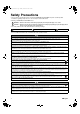
01_EN_3P255640-1.fm Page 1 Monday, November 30, 2009 1:23 PM Safety Precautions • The precautions described herein are classified as WARNING and CAUTION. They both contain important information regarding safety. Be sure to observe all precautions without fail. • Meaning of WARNING and CAUTION notices WARNING .... Failure to follow these instructions properly may result in personal injury or loss of life. CAUTION .....
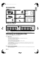
01_EN_3P255640-1.fm Page 2 Monday, November 30, 2009 1:23 PM Indoor unit English Accessories A – J , A Mounting plate D Remote controller holder 1 1 G Operation manual 1 B Titanium apatite photocatalytic air-purifying filter H Installation manual E Dry battery AAA. LR03 (alkaline) 2 2 J Paper pattern C Wireless remote controller (The paper pattern is placed between the last page and the inner side of the back cover. See page 10 for the usage of the paper pattern.
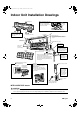
01_EN_3P255640-1.fm Page 3 Monday, November 30, 2009 1:23 PM Indoor Unit Installation Drawings n How to attach the indoor unit A Mounting plate A Mounting plate Hook the claws of the bottom frame to the mounting plate. If the claws are difficult to hook, remove the front grille. Clip Front grille The mounting plate should be installed on a wall which can support the weight of the indoor unit.
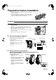
01_EN_3P255640-1.fm Page 4 Monday, November 30, 2009 1:23 PM 1. English Preparation before Installation Removing and installing front panel • Removal method 1) Hook fingers on the indentations on the left and right sides of the indoor unit, and open the front panel to a position higher than the horizontal level. 2) Raise the front panel lock tabs on the left and right sides, and slide the front panel locks upward.
01_EN_3P255640-1.fm Page 5 Monday, November 30, 2009 1:23 PM Preparation before Installation 7) Wear protection gloves and insert both hands under the front grille as shown in the illustration. 8) Remove the front grille from the 3 upper hooks by pushing up the top side of the front grille, pull the front grille toward you by holding both ends of the front grille, and dismount the front grille. 1) Push up. Upper hooks 2) Pull toward you. CAUTION • Be sure to wear protection gloves.
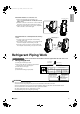
• Attachment methods of connection cord English 01_EN_3P255640-1.fm Page 6 Monday, November 30, 2009 1:23 PM HA connector (S21) 1) Remove the metal plate electrical wiring cover. (Refer to the Removal methods of metal plate electrical wiring covers.) 2) Attach the connection cord to the S21 connector and pull the harness out through the notched part in the figure. 3) Replace the electrical wiring cover as it was, and pull the harness around, as shown in the figure.
01_EN_3P255640-1.fm Page 7 Monday, November 30, 2009 1:23 PM Refrigerant Piping Work 2. Refrigerant piping CAUTION • Use the flare nut fixed to the main unit. (To prevent cracking of the flare nut by aged deterioration.) • To prevent gas leakage, apply refrigeration oil only to the inner surface of the flare. (Use refrigeration oil for R410A.) • Use torque wrenches when tightening the flare nuts to prevent damage to the flare nuts and gas leakage.
01_EN_3P255640-1.fm Page 8 Monday, November 30, 2009 1:23 PM 1. English Indoor Unit Installation Installing the mounting plate • The mounting plate should be installed on a wall which can support the weight of the indoor unit. 1) Temporarily secure the mounting plate to the wall, make sure that the unit is completely level, and mark the boring points on the wall. 2) Secure the mounting plate to the wall with screws.
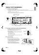
01_EN_3P255640-1.fm Page 9 Monday, November 30, 2009 1:23 PM Indoor Unit Installation 4. Laying piping, hoses, and wiring • The recommended installation method is back piping. • When performing side piping (b), refer to 5. Side piping on page 10. In the case of bottom piping (c), refer to 6. Bottom piping on page 10. Bind refrigerant pipe and drain hose together with adhesive vinyl tape. 4-1. Right-back piping 1) Attach the drain hose to the underside of the refrigerant pipes with adhesive vinyl tape.
9) While exercising care so that the inter-unit wiring do not catch indoor unit, press the bottom edge of indoor unit with both hands until it is firmly caught by the mounting plate hooks. Secure indoor unit to the mounting plate with indoor unit fixing screws (M4 × 12L). English 01_EN_3P255640-1.fm Page 10 Monday, November 30, 2009 1:23 PM A Mounting plate Drain hose Refrigerant pipes Bottom frame F Indoor unit fixing screw (M4 × 12L) (2 point) 4-3.
01_EN_3P255640-1.fm Page 11 Monday, November 30, 2009 1:23 PM Indoor Unit Installation 7. Wiring With a multi indoor unit , install as described in the installation manual supplied with the multi outdoor unit. 1) Strip wire ends (15mm). 2) Match wire colours with terminal numbers on indoor and outdoor unit’s terminal blocks and firmly screw wires to the corresponding terminals. 3) Connect the earth wires to the corresponding terminals.
01_EN_3P255640-1.fm Page 12 Monday, November 30, 2009 1:23 PM 1. English Trial Operation and Testing Trial operation and testing 1-1 Measure the supply voltage and make sure that it falls in the specified range. 1-2 Trial operation should be carried out in either cooling or heating mode. • In cooling mode, select the lowest programmable temperature; in heating mode, select the highest programmable temperature. 1) Trial operation may be disabled in either mode depending on the room temperature.
10_TR_3P255640-1.
10_TR_3P255640-1.
00_CV_3P255640-1.fm Page 2 Friday, November 13, 2009 10:51 AM Two-dimensional bar code is a code for manufacturing.