
Service manual
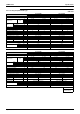
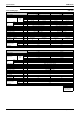

Printed Circuit Board Connector Wiring Diagram SiEBE12-625
38 Printed Circuit Board Connector Wiring Diagram
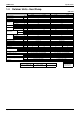
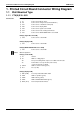
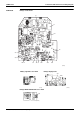
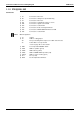
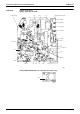
1.1.2 FTK(X)S20~35C
Connectors
Note: Other designations
1) S1 Connector for fan motor
2) S6 Connector for swing motor (Horizontal Flap)
3) S7 Connector for fan motor
4) S21 Connector for centralized control to 5 rooms
5) S26 Connector for signal receiver PCB
6) S27 Connector for control PCB
7) S32 Connector for heat exchanger thermistor
8) S35 Connector for INTELLIGENT EYE Sensor PCB
9) S36 Connector for control PCB
1) V1 Varistor
2) JA Address setting jumper
JB Fan speed setting when compressor is OFF on thermostat
JC Power failure recovery function
∗ Refer to page 291 for more detail.
3) SW7 Forced operation ON/OFF switch
4) LED1 LED for operation (green)
5) LED2 LED for timer (yellow)
6) LED3 LED for HOME LEAVE operation (red)
7) LED A LED for service monitor (green)
8) FU1 Fuse (3.15A)
9) RTH1 Room temperature thermistor