
Service manual

SiEBE12-625 Outdoor Unit (68 / 75 Class)
Removal Procedure 281
7
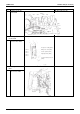
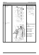
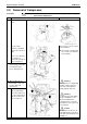
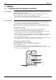
The figure shows the
control PCB.
Glass tube fuse 3A
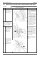
2. Removing the service
monitor PCB
1
The figure shows the
service monitor PCB.
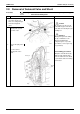
3. Removing the inverter
PCB.
1
Remove the 7 screws
of the inverter PCB.
Step
Procedure Points
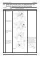
S93
S92
S40
S20S21S22
S23
S80
FU2
S90
S6
Varistor
S31
S71
S33
LED A
LED 1
LED 2
LED 3
LED 4
Priority-room setting (SW4)
Wiring error check (SW3)
Forced operation (SW1)
Night quiet mode (SW5)
Cooling / heating mode lock
(SW2)
Fuse 3A