technical data Wall Mounted Inverter Controlled Unit Split Sky Air air conditioning systems FTK/FTX(D)-JA/H/J
Split - Sky Air ISO14001 assures an effective environmental management system in order to help protect human health and the environment from the potential impact of our activities, products and services and to assist in maintaining and improving the quality of the environment Daikin Europe N.V. is approved by LRQA for its Quality Management System in accordance with the ISO9001 standard.
• Wall Mounted Inverter Controlled Unit • R-22 • FTK/FTX-JA/FTX-H/FTXD-J TABLE OF CONTENTS FTK/FTX(D)-JA/H/J 1 Features 2 Specifications 2 ................................................................................. 3 ....................................................................... Nominal capacity, capacity steps and nominal input Technical specifications Electrical specifications 3 Dimensional drawings ..................................................... 6 4 Piping diagrams .
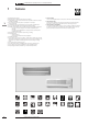
• Wall Mounted Inverter Controlled Unit • R-22 • FTK/FTX-JA/FTX-H/FTXD-J 1 2 1 Features + Lightweight and compact + Extremely quiet in operation both indoors and outdoors + A silent button on the remote control lowers the operation sound of the outdoor unit (RXD-J) by 3dB(A) + The movement sensor saves power consumption in unoccupied rooms (FTK/FTX-JA) + A comfortable sleeping mode pledges you a good night’s rest (FTK/FTX-JA) + The home leave operation saves energy during absence.
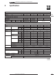
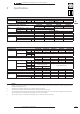
• Wall Mounted Inverter Controlled Unit • R-22 • FTK/FTX-JA/FTX-H/FTXD-J 2 Specifications NOMINAL CAPACITY and NOMINAL INPUT For indoor units only: INDOOR UNITS NOMINAL INPUT Cooling FTK25JAV1NB 0.04 FTK35JAV1NB 0.04 FTK25JAV1NB RK25JV1NB 1.30∼2.50∼3.00 0.43∼0.945∼1.250 FTK35JAV1NB RK35JV1NB 1.40∼3.54∼3.80 0.47∼1.345∼1.72 FTK25JAV1NB 273 784 185 7.5 FTK35JAV1NB 273 784 185 7.5 38 32 26 54 7.1 5.9 4.6 39 33 27 55 7.4 6 4.
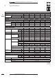
• Wall Mounted Inverter Controlled Unit • R-22 • FTK/FTX-JA/FTX-H/FTXD-J 2 2 2 Specifications NOMINAL CAPACITY and NOMINAL INPUT For indoor units only: INDOOR UNITS NOMINAL INPUT Cooling Heating FTX25JAV1NB 0.04 0.04 FTX35JAV1NB 0.04 0.04 FTXD50JV1B 0.04 0.038 FTXD60JV1B 0.045 0.045 FTXD71JV1B 0.05 0.05 FTX25JAV1NB RX25JV1NB 1.30∼2.50∼3.00 1.30∼3.40∼4.00 0.35∼0.98∼1.35 0.35∼1.130∼1.350 FTX35JAV1NB RX35JV1NB 1.40∼3.43∼3.80 1.40∼4.10∼5.10 0.50∼1.43∼1.72 0.405∼1.375∼1.90 FTXD50JV1B RXD50JV1B 0.
• Wall Mounted Inverter Controlled Unit • R-22 • FTK/FTX-JA/FTX-H/FTXD-J 2 Specifications ELECTRICAL SPECIFICATIONS For indoor units only: CURRENT Nominal running current Maximum running current cooling cooling FTK25JAV1NB 0.
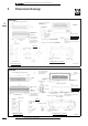
• Wall Mounted Inverter Controlled Unit • R-22 • FTK/FTX-JA/FTX-H/FTXD-J 3 2 Dimensional drawings unit (mm) FTK25-35JA The mark (Y) shows piping direction 3 Air flow (indoor) required space (for performance and maintenance) Rear Left Right Terminal strip with earth terminal Room temp.
• Wall Mounted Inverter Controlled Unit • R-22 • FTK/FTX-JA/FTX-H/FTXD-J 3 Dimensional drawings unit (mm) FTX25-35JA The mark (Y) shows piping direction Air flow (indoor) required space (for performance and maintenance) Rear Left (space for maintenance) Intelligent eye sensor indicator lamp (space for maintenance) Note: Gas pipe specification Name plate Signal receiver Flaps Terminal strip with earth terminal Room temp.
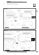
• Wall Mounted Inverter Controlled Unit • R-22 • FTK/FTX-JA/FTX-H/FTXD-J 4 2 4 Piping diagrams FTK25-35JA FTX25-35JA Indoor unit Heat exchanger Thermistor on heat exchanger Cross flow fan Field piping Fan motor Field piping A FTK25FTX25FTK35FTX35- 9.5 12.7 4D019960D FTK50-60H Indoor unit Heat exchanger Note: 1. Gas pipe specification A FTK50 FTK60 12.7 15.
• Wall Mounted Inverter Controlled Unit • R-22 • FTK/FTX-JA/FTX-H/FTXD-J 4 Piping diagrams FTXD50∼71J 2 Indoor unit 4 Thermistor on inlet pipe Heat exchanger Thermistor on heat exchanger Field piping Note: 1. Gas pipe specification FTXD50 FTXD60 FTXD71 Field piping A B 12.7 15.9 15.9 6.4 6.4 9.
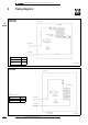
• Wall Mounted Inverter Controlled Unit • R-22 • FTK/FTX-JA/FTX-H/FTXD-J 5 2 Wiring diagrams FTK25-35JA 5 Intelligent eye sensor (Terminal for centralised control) Outdoor g Field wiring Caution Note that operation will restart automatically if the main power supply is turned off and then back on again.
• Wall Mounted Inverter Controlled Unit • R-22 • FTK/FTX-JA/FTX-H/FTXD-J 5 Wiring diagrams 2 FTX25-35JA 5 Intelligent eye sensor Outdoor (Terminal for centralised control) g Field wiring Caution Note that operation will restart automatically if the main power supply is turned off and then back on again.
• Wall Mounted Inverter Controlled Unit • R-22 • FTK/FTX-JA/FTX-H/FTXD-J 6 6-1 2 Sound level data Cooling only Sound pressure level 6 6-1 Sound level 230V Model 50Hz Measuring location H L FTK25JAV1NB 38 26 FTK35JAV1NB 39 27 FTK50HV1NB 44 35 FTK60HV1NB 46 38 Location of microphone Sound power level (H) 54 55 Indoor unit 60 Center 62 Heating only Sound pressure level 230V Model 12 50Hz H (cooling/heating) L (cooling/heating) FTX25JAV1NB 38/38 26/26 FTX35JAV1NB 39/39 2
• Wall Mounted Inverter Controlled Unit • R-22 • FTK/FTX-JA/FTX-H/FTXD-J 6 6-2 Sound level Sound pressure spectrum Cooling only FTK25JAV1NB 2 FTK35JAV1NB 6 Octave band sound pressure level dB:(0dB = 0.0002 µ bar) Octave band sound pressure level dB:(0dB = 0.
• Wall Mounted Inverter Controlled Unit • R-22 • FTK/FTX-JA/FTX-H/FTXD-J 6 6-2 2 Sound level Sound pressure spectrum FTX25JAV1NB (Heating) FTX25JAV1NB (Cooling) 6 Octave band sound pressure level dB:(0dB = 0.0002 µ bar) Octave band sound pressure level dB:(0dB = 0.
• Wall Mounted Inverter Controlled Unit • R-22 • FTK/FTX-JA/FTX-H/FTXD-J 6 6-2 Sound level Sound pressure spectrum FTXD50JV1B (Heating) FTXD50JV1B (Cooling) 2 6 Octave band sound pressure level dB:(0dB = 0.0002 µ bar) Octave band sound pressure level dB:(0dB = 0.
• Wall Mounted Inverter Controlled Unit • R-22 • FTK/FTX-JA/FTX-H/FTXD-J 6 6-2 2 Sound level Sound pressure spectrum FTXD71JV1B (Heating) FTXD71JV1B (Cooling) 6 Octave band sound pressure level dB:(0dB = 0.0002 µ bar) Octave band sound pressure level dB:(0dB = 0.
• Wall Mounted Inverter Controlled Unit • R-22 • FTK/FTX-JA/FTX-H/FTXD-J 7 Air flow patterns FTX35JA (Cooling Discharge Angle: 0°) 2 Cooling - air velocity distribution 7 FTX35JA (Heating Discharge Angle: 0°) Cooling - air temperature distribution NOTES To make the air current analysis graphical, the results calculated in the axial flow characteristic equation are used. Keep in mind that the actual results depend on the insulating performance of a house and the layout of furniture.
• Wall Mounted Inverter Controlled Unit • R-22 • FTK/FTX-JA/FTX-H/FTXD-J 7 2 Air flow patterns FTX35JA (Cooling Discharge Angle: 45°) Cooling - air velocity distribution 7 FTX35JA (Heating Discharge Angle: 45°) Cooling - air temperature distribution NOTES To make the air current analysis graphical, the results calculated in the axial flow characteristic equation are used. Keep in mind that the actual results depend on the insulating performance of a house and the layout of furniture.
• Wall Mounted Inverter Controlled Unit • R-22 • FTK/FTX-JA/FTX-H/FTXD-J 7 Air flow patterns FTXD60J (Cooling Discharge Angle: 15°) 2 Cooling - air velocity distribution 7 FTXD60J (Heating Discharge Angle: 15°) Cooling - air temperature distribution NOTES To make the air current analysis graphical, the results calculated in the axial flow characteristic equation are used. Keep in mind that the actual results depend on the insulating performance of a house and the layout of furniture.
• Wall Mounted Inverter Controlled Unit • R-22 • FTK/FTX-JA/FTX-H/FTXD-J 7 2 Air flow patterns FTXD60J (Cooling Discharge Angle: 40°) Cooling - air velocity distribution 7 FTXD60J (Heating Discharge Angle: 40°) Cooling - air temperature distribution NOTES To make the air current analysis graphical, the results calculated in the axial flow characteristic equation are used. Keep in mind that the actual results depend on the insulating performance of a house and the layout of furniture.
• Wall Mounted Inverter Controlled Unit • R-22 • FTK/FTX-JA/FTX-H/FTXD-J 8 8-1 Accessories Standard accessories j A Mounting plate 1 j B Mounting plate fixing screw M4 x 25L 25/35 class 6 50/60 class 10 j E Remote control holder z1 1 j J Insulation tape (25/35 class only) 1 j F Fixing screw for remote control holder M3 x 20L 2 j K Operation manual 1 j C Air purification filter 2 j G AAA dry-cell batteries 2 j L Installation manual 1 j D Remote control 1 j H Indoor unit fixing screw
• Wall Mounted Inverter Controlled Unit • R-22 • FTK/FTX-JA/FTX-H/FTXD-J 9 9-1 2 Control systems Infrared remote control FTK25-35JAV1NB 9 9-1 Transmitter Display It displays the current settings. (In this illustration, each section is shown with all its displays ON for the purpose of explanation. Some models may not show all its indications.) Open the cover Sends signals to the indoor unit. TEMPERATURE/TIME adjustment buttons Change the temperature or time setting.
• Wall Mounted Inverter Controlled Unit • R-22 • FTK/FTX-JA/FTX-H/FTXD-J 9 9-1 Control systems Infrared remote control FTK50-60HV1NB 2 Transmitter Sends signals to the indoor unit. On/Off button 9 9-1 Press it once to start operation. To stop it, press it once again. Display Display the current settings. (In this illustration, each section is shown with all its displays ON for the purpose of explanation.
• Wall Mounted Inverter Controlled Unit • R-22 • FTK/FTX-JA/FTX-H/FTXD-J 9 9-1 2 Control systems Infrared remote control FTX25-35JAV1NB 9 9-1 Transmitter Display It displays the current settings. (In this illustration, each section is shown with all its displays ON for the purpose of explanation. Some models may not show all its indications.) Open the cover Sends signals to the indoor unit. TEMPERATURE/TIME adjustment buttons Change the temperature or time setting.
• Wall Mounted Inverter Controlled Unit • R-22 • FTK/FTX-JA/FTX-H/FTXD-J 9 9-1 Control systems Infrared remote control 2 FTXD50,60,71JV1B 9 9-1 Open the cover Transmitter It sends signals to the indoor unit. On/Off button Press it once to start operation. To stop it, press it once again. Display It displays the current settings. (In this illustration, each section is shown with all its displays ON for the purpose of explanation.
• Wall Mounted Inverter Controlled Unit • R-22 • FTK/FTX-JA/FTX-H/FTXD-J 10 Centre of gravity 2 10 FTK25-35JAV1NB FTX25-35JAV1NB 4D020686D FTXD50-60-71JV1B 4D027652 26 • Split - Sky Air • Indoor Units
• Wall Mounted Inverter Controlled Unit • R-22 • FTK/FTX-JA/FTX-H/FTXD-J 11 Installation 2 Indoor/outdoor unit installation drawings 11 How to attach the indoor unit. Hook the claws of the bottom frame to the mounting plate. If the claws are difficult to hook, remove the front panel. Mounting plate How to remove the indoor unit. Push up the marked area (at the lower part of the front panel) to release the claws. If it is difficult to release, remove the front panel.