00_CV_3P190114-1D.
FTKS50FV1B, FTKS60FV1B, FTKS71FV1B, FTXS50FV1B, FTXS60FV1B, FTXS71FV1B, FTX50GV1B, FTX60GV1B, FTX71GV1B, FTYN50FV1B, FTYN60FV1B, FTN50FV1B, FTN60FV1B DAIKIN INDUSTRIES, LTD. Shinri Sada Manager Quality Control Department 25th. of Nov. 2009 Low Voltage 2006/95/EC Electromagnetic Compatibility 2004/108/EC * Umeda Center Bldg., 2-4-12, Nakazaki-Nishi, Kita-ku, Osaka, 530-8323 Japan 74736-KRQ/EMC97-4957 KEMA Quality B.V. DAIKIN.TCF.015 M18/11-2009 3SB64526-5F.
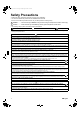
01_EN_3P190114-1D.fm Page 1 Monday, August 23, 2010 3:35 PM Safety Precautions • Read these Safety Precautions carefully to ensure correct installation. • This manual classifies the precautions into WARNING and CAUTION. Be sure to follow all the precautions below: they are all important for ensuring safety. WARNING...............Failure to follow any of WARNING is likely to result in such grave consequences as death or serious injury. CAUTION...............
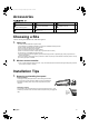
01_EN_3P190114-1D.fm Page 2 Monday, August 23, 2010 3:35 PM Accessories ) – L ) Mounting plate 1 - Remote controller holder 1 K * Titanium Apatite Photocatalytic Air-Purifying Filter 2 / AAA dry-cell batteries 2 L Installation manual , Wireless remote controller 1 0 Indoor unit fixing screws (M4 × 12L) 2 Operation manual 1 1 Choosing a Site • Before choosing the installation site, obtain user approval. 1. Indoor unit.
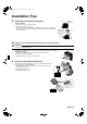
01_EN_3P190114-1D.fm Page 3 Monday, August 23, 2010 3:35 PM Installation Tips 2. Removing and installing front grille. ¡¡¡ mark area Upper hook (3 locations) • Removal method 1) Remove front panel to remove the air filter. 2) Remove the front grille. (3 screws) 3) In front of the {{{ mark of the front grille, there are 3 upper hooks. Lightly pull the front grille toward you with one hand, and push down on the hooks with the fingers of your other hand.
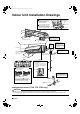
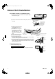
01_EN_3P190114-1D.fm Page 4 Monday, August 23, 2010 3:35 PM Indoor Unit Installation Drawings How to attach the indoor unit. Hook the claws of the bottom frame to the mounting plate. If the claws are difficult to hook, remove the front grille. How to remove the indoor unit. Push up the marked area (at the lower part of the front grille) to release the claws. If it is difficult to release, remove the front grille.
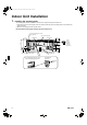
01_EN_3P190114-1D.fm Page 5 Monday, August 23, 2010 3:35 PM Indoor Unit Installation 1. Installing the mounting plate. • The mounting plate should be installed on a wall which can support the weight of the indoor unit. 1) Temporarily secure the mounting plate to the wall, make sure that the panel is completely level, and mark the boring points on the wall. 2) Secure the mounting plate to the wall with screws.
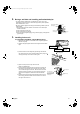
01_EN_3P190114-1D.fm Page 6 Monday, August 23, 2010 3:35 PM 2. Boring a wall hole and installing wall embedded pipe. • For walls containing metal frame or metal board, be sure to use a wall embedded pipe and wall cover in the feed-through hole to prevent possible heat, electrical shock, or fire. • Be sure to caulk the gaps around the pipes with caulking material to prevent water leakage. 1) Bore a feed-through hole of 80mm in the wall so it has a down slope toward the outside.
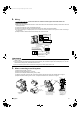
01_EN_3P190114-1D.fm Page 7 Monday, August 23, 2010 3:35 PM Indoor Unit Installation 3-2. Left-Side, Left-Back, or Left-Bottom Piping Remove pipe port cover here for leftside piping 1) Attach the drain hose to the underside of the refrigerant pipes with adhesive vinyl tape. Left-side piping Left-back piping Remove pipe port cover here for left-bottom piping Left-bottom piping 2) Be sure to connect the drain hose to the drain port in place of a drain plug.
01_EN_3P190114-1D.fm Page 8 Monday, August 23, 2010 3:35 PM 4. Wiring. With a Multi indoor unit , install as described in the installation manual supplied with the Multi outdoor unit. 1) Strip wire ends (15mm). 2) Match wire colours with terminal numbers on indoor and outdoor unit’s terminal blocks and firmly screw wires to the corresponding terminals. 3) Connect the earth wires to the corresponding terminals.
01_EN_3P190114-1D.fm Page 9 Monday, August 23, 2010 3:35 PM Indoor Unit Installation 6. Drain piping. The drain hose should be inclined downward. 1) Connect the drain hose, as described right. No trap is permitted. Do not put the end of the hose in water. 2) Remove the air filters and pour some water into the drain pan to check the water flows smoothly. Indoor unit drain hose Extension drain hose φ18 3) When drain hose requires extension, obtain an extension hose commercially available.
01_EN_3P190114-1D.fm Page 10 Monday, August 23, 2010 3:35 PM 2. Refrigerant piping. CAUTION 1) Use the flare nut fixed to the main unit. (To prevent cracking of the flare nut by aged deterioration.) 2) To prevent gas leakage, apply refrigeration oil only to the inner surface of the flare. (Use refrigeration oil for R410A.) 3) Use torque wrenches when tightening the flare nuts to prevent damage to the flare nuts and gas leakage.
01_EN_3P190114-1D.fm Page 11 Monday, August 23, 2010 3:35 PM Trial Operation and Testing 1. Trial operation and testing. 1-1 Measure the supply voltage and make sure that it falls in the specified range. 1-2 Trial operation should be carried out in either cooling or heating mode. ■ For Heat pump • In cooling mode, select the lowest programmable temperature; in heating mode, select the highest programmable temperature. 1) Trial operation may be disabled in either mode depending on the room temperature.
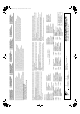
00_CV_3P190114-1D.fm Page 2 Monday, August 23, 2010 3:29 PM Two-dimensional bar code is a code for manufacturing.